13
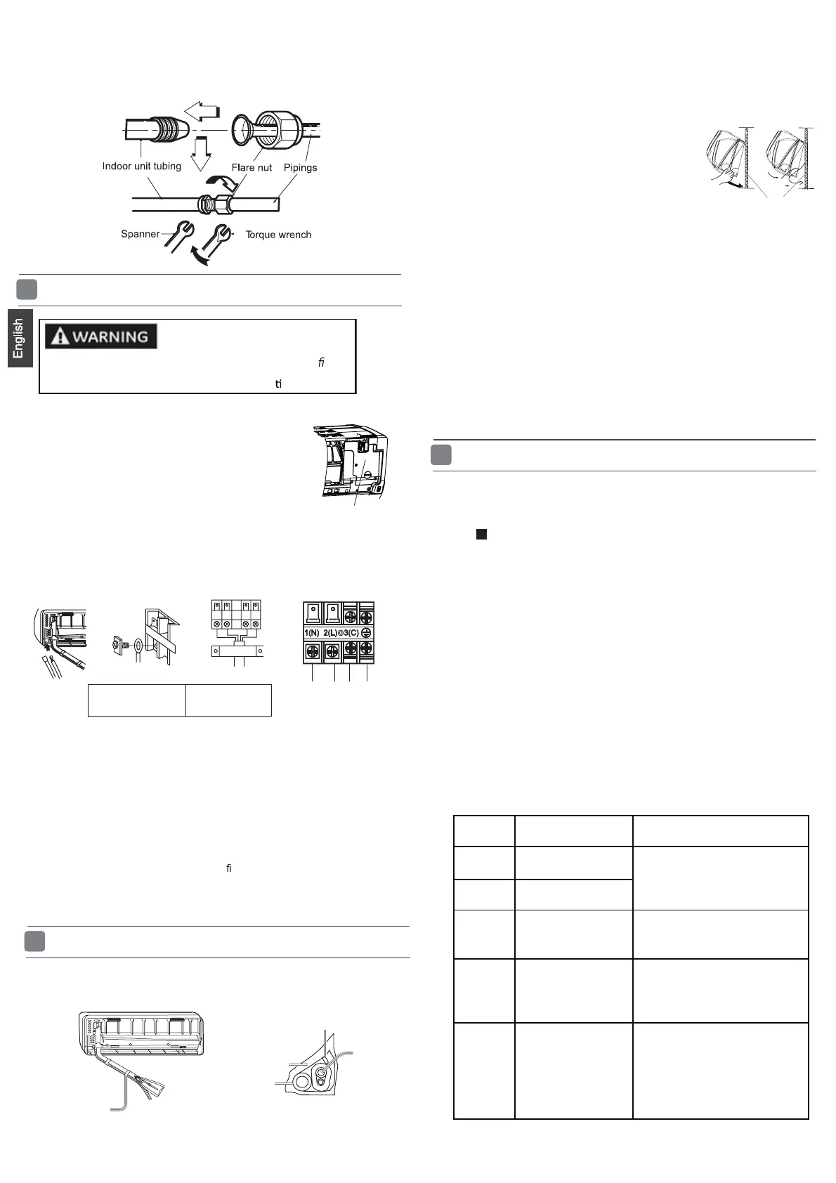
Conne ction of wirings and drain pipe
6
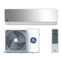
1. Open the cover A to expose the electrical box.
2. Insert the connecting wiring from the rear of the unit
then pull it out of the front.
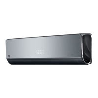
3. Loosen the cable clamp and ensure the cable is fed
through the cable strain relief clamp.
4. Loosen the terminal block screws and insert the
connecting wiring ends fully into the terminal block.
Then tighten the screws in the terminal block.
5.Pull the wiring slightly to make sure the wiring has been properly inserted
and tightened.
6. Tighten the cable strain relief clamp.
7. Replace the cover A.
cover A
RISK OF ELECTRIC SHOCK OR FIRE. Only suitably quali ed
personnel should make the electrical connec
ons.
To Outdoor unit
Indoo r unit
Connecting wiring
4G 1.0 mm
2
8. Install the drain pipe.
1. If the supply cord is damaged, it must be replaced by the manufacturer or its
service agent . The typeofconnecting wire is
H07RN -F.
2.IfthefuseonPCboardisbrokenpleasechangeitwiththe
type of
3. The wiring method should be in line with the local wiring standard.
4. A breaker shou ld be incorporated into
xed wiring. T he breaker should be
all-pole
switch and the distance between its two contacts should be not less
than 3mm.
T.3.15A/250VA C (Indoor).
Attention:
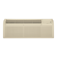
Fixing the indoor unit body
7
1. Wrap the pipes, connecting wirings and drain pipe as follows. Cover them with
heat insulation materials closely and fi x with adhes ive tape.
Fix with adhes ive tape
Drain hose
Piping
Indoor/outdoor connne cting wiring
Heat insulation materials
them through the wall hole to the outdoor
.
3. Hang surely the unit body onto the upper
notches of the
mounting plate. Move the body
from
side to side to verify its
se cure fixing.
4. In order to fix the body onto the mounting
plate,hold up
the body aslant from the
underside and
then put it down
perpendicularly.
mounting plate
2. Make
.
1.Keep the drain pipe in the warm area to prevent condensation. Problems
with the piping may lead to water leaks and interior property damage.
2.Do not install the drain pipe as follows.
It is raised after exiting the wall.
The end is immersed in water.
It has raised sections near the ground.
Too close to the ground.
The end of the hose is near to drains with bad odours.
3. Pour water in the drain pan of the indoor unit to confirm the
drainage is carried out to the outside of the building without problems.
Attention:
Please kindly explain to our customers how to
operate
throug h t he in s tr u c t io n manua l.
8
Che ck installation and test run
Refer to the other instructions to install the outdoor unit. Check and
ensure the indoor and outoor units are securely installed. Then put
the power on to test run.
Are there any gas leaks from the connecting pipes or connections?
Has insulation been wrapped around the connecting pipes?
Are the connecting cables properly inserted in the terminal blocks and fully tightened?
Is the drainage working properly?
Is the indoor unit securely fixed to the wall?
Is power s ource voltage the same as the rated voltage of the product?
Is there any unusual noise coming from the indoor or outdoor units?
Are the lights/displays working properly?
Are cooling and heating (when in heat pump) working properly?
Is the temperature control working properly?
Does the remote control work properly?
Attention:
After the installation of the indoor and outdoor unit, put the
power on to test. Th e referen ce indoor fault codes are as
follows.
Code
indication
Trouble description
Analyze and diagnose
E1
E2
E4
E7
E14
Piping
temperature
sensor failure
Indoor EEPROM
error
C ommunication
fault between
indoor and outdoor
units
Indoor fan motor
malfunction
Operation halt due to
fan
Detection error due to faulty
indoor unit PCB;
Indoor unit- outdoor unit signal
transmission error du
e to wiring
error;
Faulty PCB;
Faulty EEPROM data;
Faulty EEPROM;
Faulty PCB;
Faulty connector connection;
Faulty thermistor;
Faulty PCB;
Room temperature
sensor failure
motor fault;