This document describes the SF6 circuit-breaker GL317D, equipped with FK3-4 spring operating mechanisms, and serves as an instruction manual covering its installation, commissioning, operation, inspection, maintenance, and reconditioning.
Function Description:
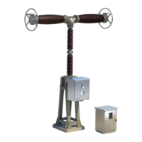
The GL317D circuit-breaker is a high-voltage switchgear unit designed for electrical arc quenching using pressurized SF6 gas or an SF6+CF4 gas mixture. It is composed of three poles, each activated by a spring operating mechanism. The circuit-breaker's primary function is to interrupt electrical circuits under various conditions, including short-circuits, and to provide insulation. Each pole consists of interrupting chambers, a support column, and a housing for the mechanism. The operating device is a spring operating mechanism of the FK3-4 type, typically electrically remote-controlled, but also capable of direct manual operation for commissioning or when auxiliary voltage is unavailable. A marshalling cubicle, fastened to the ground near the central pole, houses the relays and interconnection terminal boards required for operation.
Important Technical Specifications:
- SF6 Gas: The quenching medium is pressurized SF6 gas or an SF6+CF4 gas mixture. SF6 is a fluorinated greenhouse gas with a Global Warming Potential (GWP) of 22,200, emphasizing the need for recovery and prevention of release into the atmosphere.
- Interrupting Principle: Thermal blasting type, utilizing arc energy with an auxiliary autopneumatic effect.
- Operating Mechanism: FK3-4 spring operating mechanism.
- Pressure Monitoring: Permanent monitoring with a threshold densimeter and periodic visual control with a dial densimeter.
pre: Filling rated pressure for insulation.pae: Alarm pressure for insulation.pme: Minimal pressure for insulation.
- Pressure Units: Pascal (Pa) is the international unit; bar (1 bar = 1,000 hPa = 100 kPa = 0.1 MPa) is the practical unit. Standard atmospheric pressure is 101.3 kPa at 20°C (68°F).
- Electrical Resistance: The electrical resistance value of the assembly should be R ≤ 2µΩ.
- Tightening Torques: Specific tightening torques are provided for steel screws (Class 6.8 and Class 8.8) ranging from M2.5 (0.05 daN.m for Class 6.8) to M30 (90.44 daN.m for Class 6.8).
- Operating Times (at rated voltage):
- Closing: 92-112 ms
- Opening O1/O2: 18-26 ms
- Closing of CO: 92-112 ms
- Opening of CO: 40-56 ms
- CO: 45-70 ms
- 1st Opening of O-CO: 18-26 ms
- Closing of O-CO: 92-112 ms
- 2nd Opening of O-CO: 40-56 ms
- Resistor insertion on closing: 5.5-9.0 ms
- Relay Timings (Allen Bradley/FINDER at nominal voltage):
- Closing: 16-28 ms (Allen Bradley), 7-13 ms (FINDER)
- Opening: 16-28 ms (Allen Bradley), 7-13 ms (FINDER)
- Auxiliary Contact Timings:
- Type a / Closing of CO: 98-128 ms
- Type b / Closing of CO: 75-105 ms
- Type a / Opening of CO: 26-56 ms
- Type b / Opening of CO: 37-67 ms
- Type a / 1st Opening of O-CO: 9-22 ms
- Type b / 1st Opening of O-CO: 20-33 ms
- Type a / Closing of O-CO: 98-128 ms
- Type b / Closing of O-CO: 75-105 ms
- Type a / 2nd Opening of O-CO: 26-56 ms
- Type b / 2nd Opening of O-CO: 37-67 ms
- Deviation between Chambers (same pole): Max 2 ms for Closing/Opening.
- Deviation between Poles: Max 5 ms for Closing, 3 ms for Opening.
- Charging Time: Max 10 seconds for all motor voltages.
- Main Circuit Resistance (without HV terminal, 100 A DC): Max 90-95 µΩ depending on chamber type.
- Electrical Wear Limits: Determined by the formula ΣNI² = 20,000 kA² (N = number of interruptions on value I). For example, 50 interruptions at 20 kA are possible.
Usage Features:
- Installation: Detailed procedures for erection, including general instructions, tightening torques, checking for nitrogen presence in pole parts, support-frame assembly, column-chambers coupling, tipping down the pole, vacuum operation, installing terminals, installing capacitors, lifting and positioning the pole, installing the operating device, connecting the vacuum pump, SF6 gas pre-filling, and final SF6 gas filling.
- Commissioning: Pre-commissioning inspections cover pole/operating device coupling sleeve, orientation and identification of interrupting chambers, SF6 gas checks (pressure, humidity), operating device measurements and inspections (heating, lighting, connections), and finish and test operations (5 CLOSING-OPENING cycles electrically).
- Operation: The operating device uses a spring mechanism (FK3-4) for closing and opening. Optical signalization displays the circuit-breaker state (Open/Closed) and closing spring state (Loaded/Released). SF6 gas monitoring ensures performance, with a densimeter indicating absolute pressure (Green: None, Yellow: Topping-up, Red: Abnormally low density).
- Safety: Strict safety instructions are provided for all stages, including handling, installation, start-up, operation, maintenance, and scrapping/recycling. These cover personnel qualifications, equipment condition, use of appropriate tools, working area demarcation, and specific precautions for SF6 gas, pressurized equipment, electrical equipment, and moving parts. Minimum safety distances (approx. 50m for ceramic devices, height of device for composites) are specified during SF6 filling/commissioning.
Maintenance Features:
- Maintenance Plan: Defined under normal operating conditions.
- Maintenance Visits (M1): Once or twice a year, including 2 CO duty cycles to check proper functioning.
- Inspections (M2): Every five years, requiring circuit-breaker shutdown but not dismantling interrupting chambers. Includes checking SF6 densimeter thresholds and adjusting pressure.
- Overhaul (M4): Performed after 20 years of operating life or 3,000 mechanical cycles, or when electric wear limits are reached. This involves inspection of the most used pole/circuit-breaker and adapting the program for others.
- Detail of Maintenance Operations:
- General Condition: Visual inspection for corrosion, paintwork, overheating signs. Reconditioning of affected parts.
- SF6 Pressure Gas: Checking densimeter needle position (Green, Yellow, Red zones) and verifying concordance with electrical contact densimeter.
- Operating Device: Cleaning air-vents, checking permanent resistors, verifying thermally controlled resistors with a thermostat, checking opening damper for oil leaks.
- Operation Counter: Reading and noting operations to influence future maintenance.
- Electrical Densimeter Thresholds: Checking and adjusting electrical contact SF6 densimeter thresholds; replacing if outside tolerances.
- Tightening of Mountings: Checking and adjusting tightening torques of screws on sub-assemblies not subjected to gas pressure.
- Relay Operation: Checking relay operation by executing closing lock-out, automatic opening, and anti-pumping sequences.
- Tightening LV Terminals: Checking and tightening connectors and tips of conductors on terminal blocks.
- Insulating Envelopes: Checking for impact marks, splintering, cracks, dust, pollution; cleaning or replacing defective parts.
- Interrupting Chambers: Complete dismantling and inspection by Grid Solutions After-sales Service.
- Lubrication: No future lubrication is necessary; bearings and rollers are pre-lubricated with ASEOL SYLITEA 4-018 grease. Mixing with other lubricants or oils is prohibited.
- Cleaning Windows: Use exclusively soapy water; scouring pads are prohibited.
- End of Equipment Service Life: Detailed instructions for dismantling and recovery, including treatment of SF6 gas (recycling/reprocessing), recycling of metals (aluminum and copper must not be mixed), destruction of waste products by incineration, and handling of special wastes. SF6 gas handling operations must be carried out by trained and qualified personnel using specific tools and procedures to limit gas releases.