Installation
Chamber - Column Coup ling
GE Information L31- 7143EN/02
2/16
03- 2017
Checking o f the insertion resistor
Process
The table below gives the steps of checking of the insertion resistor :
Step Action Diagram
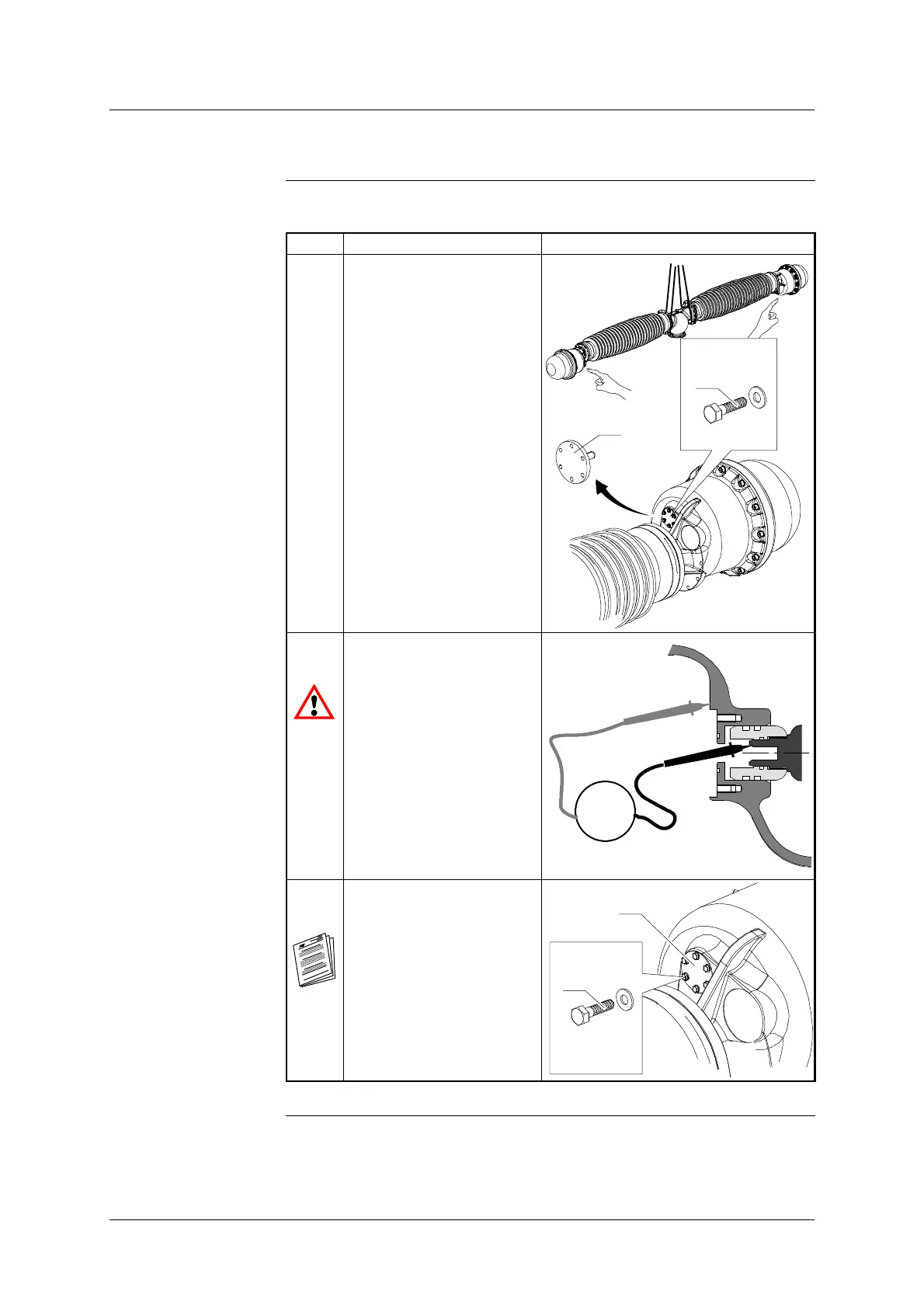
1 Using the two straps
provided, lift the chambers
(approximate weight :
700 kg).
On each resistor, remove
the plug (36) fixed by
screws (37).
36
x6
HM8-25
37
2 Measure the ohmic value
using a multimeter.
If the measured value
does not correspond to
the value indicated on the
plug, contact our Cus-
tomer Service.
Ω
3 Re- install the plugs (36)
using the screws (37), refer-
ring to “Screw sealing” in
”Erection general proced-
ures”.
Put back the chambers.
36
x6
HM8-25
1,6 daN.m
37




 To Next Page