Installation
Chamber - Column Coup ling
GE Information L31- 7143EN/02
14/16
03- 2017
Final coupling, continued
Connection
chambers/column
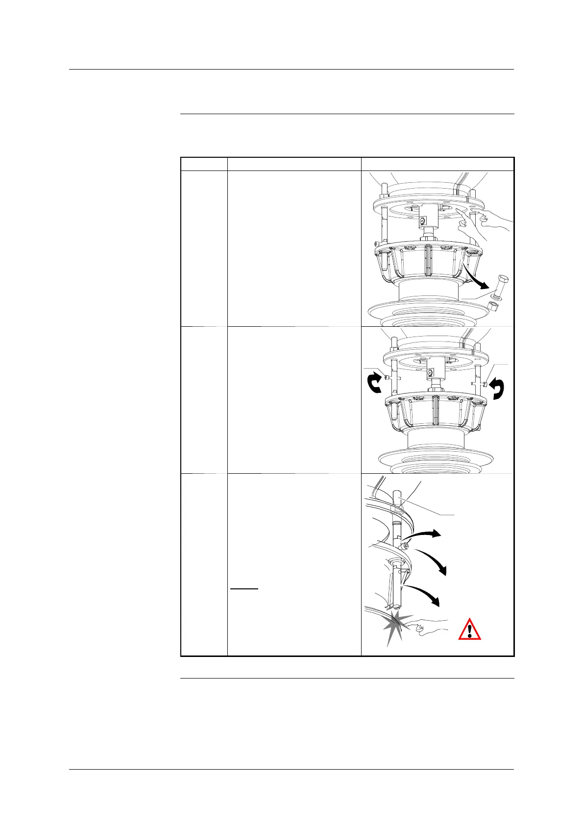
The table below shows the steps for connecting the chambers to the column:
Step Action Illustration
1 Clean the contact surfaces
”A” and ”B” with ISOPRO-
PANOL.
Only coat surface ”B” with
MOLYKOTE M111 lubricant.
Remove the trolley stop fixing
screws (40).
40
A
B
2 Remove the screws (42) from
the centring pins.
42
42
3 Continue to slowly lower the
breaking chamber, removing
the first two sections of cent-
ring pin (30 & 31) when they
are no longer of any use as a
guide, in the following order:
- First section (C)
- Screw (42)
- Second section (B)
NOTE
: The aim of this
operation is to prevent the
centring pins coming into
contact with the porcelain
fins on the column.
30
31
(C)
(B)
(42)
Continued on next page.




 To Next Page