Installation
Chamber - Column Coup ling
GE Information L31- 7142EN/02
9/18
03- 2017
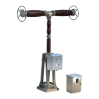
Final coupling
Orientation
of column
Rotate the column (1) so that the control mount (3) is the same side as the
two ’humps’ on the breaking chamber casing (2).
3
1
2
Assembling
the centring pins
Fit parts A, B & C to the centring pins (30) & (31) without locking them in place
so that they may be easily removed later on.
NOTE
: Pin (31) is longer than pin (30).
30
A
B
C
31
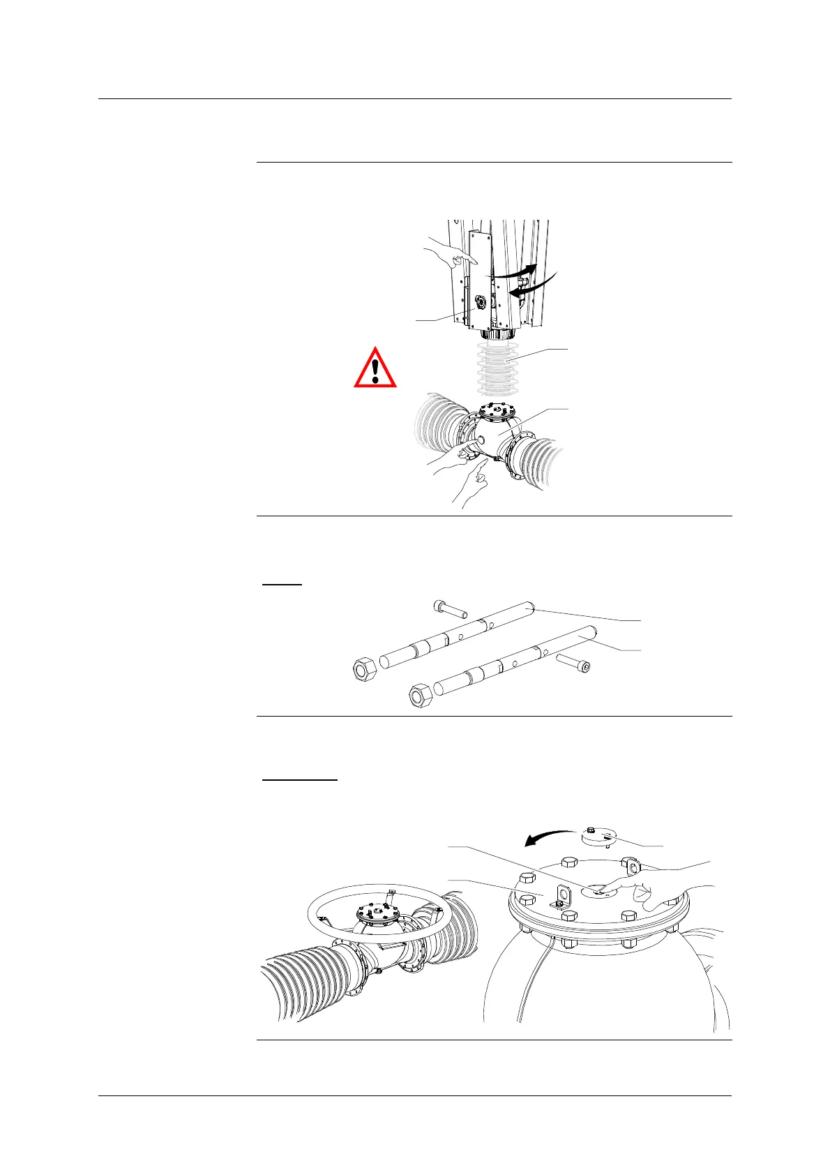
Depressurizing
the chambers
S Remove the cap (5) from the transport cover (4) and operate the valve (6)
to re- establish atmospheric pressure within the chambers.
REMINDER
: transport pressure nitrogen: azote (N
2
) at 0.03 MPa at 20C
(101.3 kPa).
S Refit the cap (5).
5
6
4
Continued on next page.