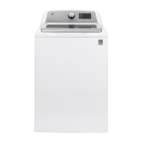
EasyManua.ls Logo

GE GMAN1200 User Manual

GE GMAN1200
8 pages
To Next Page IconTo Next Page
Page #1 background imageLoading...
Page #1 background image
“L” WASHER
IMPORTANT
Electric Discharge (ESD)
Sensitive Electronics
ESD problems are present everywhere. ESD may damage or weaken the
electronic control assembly. The new control assembly may appear to work
well after repair is finished, but failure may occur at a later date due to ESD
stress.
Use an anti-static wrist strap. Connect wrist strap to ground connection
point or unpainted metal in the appliance.
–OR–
Touch your finger repeatedly to ground connection point or unpainted
metal in the appliance.
Before removing the part from its package, touch the anti-static bag to a
green ground connection point or unpainted metal in the appliance.
Avoid touching electronic parts or terminal contact; handle electronic
control assembly by edges only.
When repackaging failed electronic control assembly in anti-static bag,
observe above-mentioned precautions.
DIAGNOSTIC GUIDE
Before testing washer operation, check the following:
Is the power cord firmly plugged into a live circuit?
Has a household fuse blown or circuit breaker tripped? Time delay fuse?
Are both hot and cold water faucets open and water supply hoses
unobstructed?
Before opening the unit make sure the washer is unplugged from power
outlet.
Check all connections before replacing components. Look for broken or
loose wires, failed terminals, or wires not pressed into connections far
enough.
The most common cause for control failure is corrosion on connectors.
Therefore, disconnecting and reconnecting wires will be necessary
throughout test procedures.
Connectors: Look at top of connector. Check for broken or loose wires.
Check for wires not pressed into connector far enough to engage metal
barbs.
Resistance check must be made with power cord unplugged from outlet,
and with wiring harness or connectors disconnected.
FOR SERVICE TECHNICIAN ONLY—DO NOT REMOVE OR DESTROY
175D6149P002
WARNING
Disconnect power before servicing.
Replace all parts and panels before operating.
Failure to do so can result in injury or death.
Electrical Shock Hazard
Programming the Control Board
The replacement control board will always enter into test mode t01 on
initial power-up.
If replacing the control board, the washer will not function until the
replacement control board has been programmed.
To program the replacement control board:
1. Reconnect power to the washer. (The display will now show “---”, which
means no model has been selected.)
2. Rotate the cycle knob until the correct model number is displayed:
Display “1” = GFWN1100, GFWN1200, GMAN1200
Display “2” = GFWH1200
Display “3” = GFWN1300
Display “4” = GFWH1300
Display “5” = GFWH1400, GFWH1405
Display “6” = GFWS1500, GFWS1505
3. Press and hold the Start key for 3 seconds (or until a second beep is
sounded).
4. Press the Power key to reset the control.
Note: If an error is made in programming the control, enter test mode and
select t01. Then repeat steps 2 through 4.

Questions and Answers:

GE GMAN1200 Specifications

General IconGeneral
BrandGE
ModelGMAN1200
CategoryWasher
LanguageEnglish

Summary

Safety and Handling Procedures

Electrical Shock Hazard Warning

Warns about disconnecting power before servicing and replacing parts before operating to prevent injury or death.

ESD Prevention and Handling

Details procedures for handling electronic components to prevent static damage, using wrist straps and anti-static bags.

Diagnostic Guide and Procedures

Pre-Service Operational Checks

Outlines essential checks before testing washer operation, such as power, fuses, and water supply.

Wiring and Connector Inspection

Emphasizes checking all wiring connections for looseness or poor contact, especially corrosion on connectors.

Control Board Programming

Model ID Selection and Programming

Guides on selecting the correct model ID and programming a replacement control board for proper washer function.

Wiring Diagrams

GFWN/GFWAN Models Wiring

Illustrates electrical connections for GFWN1100, GFWN1200, GFWN1300, and GMAN1200 washer models.

GFWH Models Wiring

Illustrates electrical connections for GFWH1400 and GFWH1405 washer models.

System and Wiring Diagrams

GFWH1200/GFWH1300 Wiring

Provides electrical wiring diagram for GFWH1200 and GFWH1300 washer models.

GFWS1500/GFWS1505 Wiring

Provides electrical wiring diagram for GFWS1500 and GFWS1505 washer models.

System Overview Drawing

Washer Component Layout

Visual representation of major washer components including Main Control, Motor, Pump, and Valves.

Control Board Connector Locations and Service Mode

Control Board Connector Map

Diagram showing the physical locations of connectors on the main control board.

Service Mode Entry and Exit

Instructions on how to enter and exit the service mode using specific button presses.

Service Test List Functions

Model ID and Error Code Tests

Tests for verifying or setting model ID and listing control-detected error codes.

Software and Component Tests

Tests for software versions, LCD/LEDs, pump, pressure switch, thermistor, heater, and steam generator.

Tumble, Spin, and Dispenser Tests

Tests to verify washer tumbling, spin cycles, and dispenser fill functions.

EOL Test Sequence

Performs the End-of-Line test sequence, typically not used during standard repair.

Detailed Test Function Descriptions

Test t01-t04: Model, Error, Software, Display Tests

Details functions for Model ID, Error Codes, Software ID, and Exercise LCD/LEDs tests.

Test t05-t07: Pump, Fill, and Pressure Switch Tests

Details functions for Pump, Fill sequence, and Pressure Switch tests, including water levels.

Test t08, t10-t12: Steam, Tumble, Spin, Dispenser Tests

Details functions for Steam, Tumble, Spin, and Dispenser fill tests across various models.

Test t13: End-of-Line Test

Describes the procedure for the End-of-Line test sequence.

Troubleshooting Chart

Fill and Drain Problem Diagnosis

Troubleshooting steps for fill problems (e.g., water valves, strainers) and drain problems (e.g., pump, hose).

Dispenser and Motor Drive Issues

Troubleshooting for dispenser problems and motor drive operation outside design limits.

Control, Sensor, and System Faults

Troubleshooting for main control, door lock, water level sensor, temperature sensor, and system contact failures.

Model Number Reference

List of Supported Washer Models

Provides a comprehensive list of washer model numbers covered by this service manual.

Related product manuals