EasyManua.ls Logo

GE GTX22EBMKWW - User Manual

GE GTX22EBMKWW
20 pages
Print Icon
To Next Page IconTo Next Page
Loading...
BEFORE YOU BEGIN
Read these instructions completely and carefully.
IMPORTANT Save these instructions for local
electrical inspector’s use.
IMPORTANT Observe all governing codes and
ordinances.
Install the clothes dryer according to the manufacturers
instructions and local codes.
Note to Installer – Be sure to leave these instructions
with the Consumer.
Note to Consumer Keep these instructions for future
reference.
Clothes dryer installation must be performed by a
qualified installer.
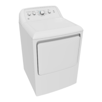
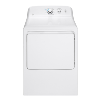
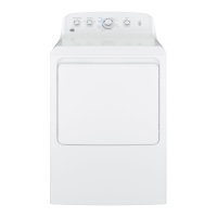
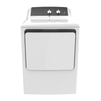
This dryer must be exhausted to the outdoors.
Before the old dryer is removed from service or
discarded, remove the dryer door.
Service information and the wiring diagram are located
in the control console.
Do not allow children on or in the appliance. Close
supervision of children is necessary when the appliance
is used near children.
Proper installation is the responsibility of the installer.
Product failure due to improper installation is not
covered under the Warranty
.
Install the dryer where the temperature is above 50°F
for satisfactory operation of the dryer control system.
and replace with UL-listed duct.
Questions? Call 800.GE.CARES (800.432.2737) or visit our Web site at: GEAppliances.ca
- Fire Hazard
WARNING
Clothes dryer installation must be performed by a
qualified installer.
Install the clothes dryer according to these
instructions and local codes.
DO NOT install a clothes dryer with flexible plastic
venting materials. If flexible metal (semi-rigid or
foil-type) duct is installed, it must be UL-listed and
installed in accordance with the instructions found
in “Connecting the Dryer to House Vent” later in
this manual. Flexible vent materials are known to
collapse, be easily crushed and trap lint. These
conditions will obstruct dryer airflow and increase
the risk of fire.
DO NOT install or store this appliance in any
location where it could be exposed to water or
weather.
To reduce the risk of severe injury or death, follow
all installation instructions.
Save these instructions. (Installers: Be sure to leave
these instructions with the customer.)
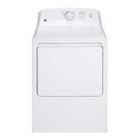
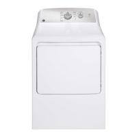
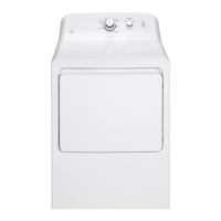
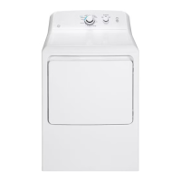
Installation Dryers
Instructions
This is the safety alert symbol. This symbol alerts you to potential hazards that can kill you or hurt you and others.
words are defined as:
Indicates a hazardous situation which, if not avoided, will result in death or serious injury.
Indicates a hazardous situation which, if not avoided, could result in death or serious injury.
Indicates a hazardous situation which, if not avoided, could result in minor or moderate injury.
DANGER
WARNING
CAUTION
29-6075 03-16 GE
Printed in Mexico
234D2318P006
Question and Answer IconNeed help?

Do you have a question about the GE GTX22EBMKWW and is the answer not in the manual?

Overview

This document provides installation instructions for GE dryers, covering both gas and electric models, as well as steam-enabled dryers. It includes critical safety warnings, rough-in dimensions, and detailed steps for connecting the appliance, exhausting it, and reversing the door swing.

Function Description:

This manual details the installation, connection, and basic setup of GE clothes dryers. It covers the process of connecting the dryer to gas or electrical supplies, venting exhaust to the outdoors, and adjusting the door swing. For steam-enabled models, it also includes instructions for connecting to a cold water supply. The overall function is to guide a qualified installer through the safe and correct setup of the dryer to ensure optimal performance and user safety.

Important Technical Specifications:

  • Rough-in Dimensions:
    • Cubic Foot 6.0: X: 43 3/8" (110 cm), Y: 26 3/4" (68 cm)
    • Cubic Foot 7.0: X: 43 3/8" (110 cm), Y: 29 1/2" (75 cm)
    • Cubic Foot 7.3: X: 43 3/4" (111 cm), Y: 30 1/2" (78 cm)
    • Side View: X: 4 5/8" (11.7 cm), Y: 4 1/4" (10.8 cm)
  • Power Cords (Not provided with dryer):
    • 3-Prong: WX9X2 (4 Feet, 30 Amps), WX9X3 (5 Feet, 30 Amps), WX9X4 (6 Feet, 30 Amps)
    • 4-Prong: WX9X18 (4 Feet, 30 Amps), WX9X19 (5 Feet, 30 Amps), WX9X20 (6 Feet, 30 Amps)
  • Electrical Supply (Gas Dryers): 120V, 60Hz, connected to a properly grounded branch circuit protected by a 15 or 20 amp circuit breaker or time delay fuse.
  • Electrical Supply (Electric Dryers): UL-listed 240V 30 amp dryer power supply cord with closed ring or spade terminals. Direct wire connections require 10 gauge copper wire.
  • Gas Supply (Gas Dryers): 1/2” rigid pipe supply line with an accessible shutoff within 6 feet of the dryer. A 1/8” NPT plugged tapping for test gauge connection is required. Maximum flexible gas connector length: 3 ft. Input ratings are based on sea level; for elevations above 2000 ft., reduce input ratings by 4 percent for each 1000 ft. above sea level.
  • Water Supply (Steam Models): Hot and cold water faucets within 42 in. (107 cm) of the washer's water inlet, 3/4 in. (1.9 cm) garden hose-type. Water pressure: 10 to 120 pounds per square inch.
  • Exhaust Ducting:
    • Rigid Metal Transition Duct: Recommended for best drying performance.
    • UL-Listed Flexible Metal Clothes Dryer Transition Duct: Total length should not exceed 8' (2.4 m). Must be UL-listed (GE parts PM08X10085, WX08X10085 or WX08X10077).
    • UL-Listed Flexible Metal (Foil-Type) Transition Duct: Used ONLY if rigid or flexible metal ducting cannot be used and a 4" diameter can be maintained. Must comply with "UL 2158A STANDARD FOR CLOTHES DRYER TRANSITION DUCT."
    • Maximum Allowable Exhaust Length (Recommended):
      • Exhaust Hood Types (4" DIA. Rigid Metal):
  • 0 Elbows: 120 Feet
  • 1 Elbow: 100 Feet
  • 2 Elbows: 85 Feet
  • 3 Elbows: 70 Feet
  • 4 Elbows: 60 Feet
  • 5 Elbows: 55 Feet
    • Exhaust Hood Types (4" DIA. Rigid Metal for short run installations):
  • 0 Elbows: 90 Feet
  • 1 Elbow: 75 Feet
  • 2 Elbows: 65 Feet
  • 3 Elbows: 55 Feet
  • 4 Elbows: 45 Feet
  • 5 Elbows: 35 Feet * Internal elbows for side or bottom vent conversions must be included in the total elbow count. Any elbow > 45° is treated as a 90° elbow. Two 45° elbows are treated as one 90° elbow. Reduce allowable vent system length by 10 feet for every additional 90° elbow.

Usage Features:

  • Alcove or Closet Installation: Requires specific clearances (0" either side, 3" front, 0" rear but 1" recommended, 1" top). Closet doors must be louvered or ventilated with at least 60 sq. inches of open area (120 sq. inches if both washer and dryer are in the closet). Gas dryers in closets must not share the space with other fuel-burning appliances.
  • Mobile or Manufactured Home Installation: Must conform to relevant safety standards (MANUFACTURED HOME CONSTRUCTION AND SAFETY STANDARD, TITLE 24, PART 32-80 or Standard CAN/CSA-Z240 MH, or ANSI/NFPA NO. 501B). Requires outdoor venting with metal duct, securely fastened, not terminated beneath the home. Kit 14-D346-33 is required for secure attachment.
  • Steam Functionality (on some models): Connects to the cold water supply via a "Y" connector, allowing both the washer and dryer to share the connection. New inlet hoses are provided and recommended.
  • Door Reversal: Detailed instructions are provided for reversing the door swing from right to left for both solid and glass panel door models. This feature allows for flexible placement and user convenience.
  • Leveling: Adjustable leveling legs and anti-tip legs ensure the dryer is stable and level, preventing tipping.
  • Power-On: Simple "Power" button activation after installation and connection.
  • Exhaust System Inspection and Cleaning: The exhaust system should be inspected and cleaned at least once a year. Access for inspection and cleaning should be provided, especially at turns and joints.
  • Duct Material: Emphasizes the use of 4" rigid metal ducting for home exhaust vents and UL-listed transition ducts to minimize fire risk and maximize drying performance. Discourages plastic vents and screens in the exhaust duct.
  • Joint Sealing: All duct joints should be tight to avoid leaks, with male ends pointing away from the dryer. Overlapped joints should be wrapped with duct tape or aluminum tape. Fasteners that extend into the duct are prohibited to prevent lint accumulation.
  • Insulation: Ductwork running through unheated areas or near air conditioning should be insulated to reduce condensation and lint buildup.
  • Gas Leak Testing: Connections must be checked for leaks using a soapy solution (not ammonia-based).
  • Water Softener Recommendation: For steam models, a water softener is recommended to reduce scale buildup in the steam generator if the home water supply is very hard.
  • Pre-Installation Lint Removal: Users are instructed to remove any lint from the wall exhaust opening before connecting the dryer.
  • Old Dryer Disposal: Before discarding an old dryer, the door should be removed for safety.

GE GTX22EBMKWW Specifications

General IconGeneral
BrandGE
ModelGTX22EBMKWW
CategoryDryer
LanguageEnglish

Related product manuals