Operating Instructions
12
Safety Instructions
Installation Instructions
Troubleshooting TipsCustomer Service
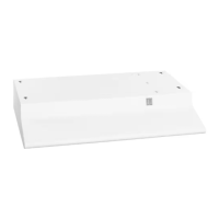
Installation of the downdraft system.
Read these instructions completely and carefully.
Installing the Downdraft
Set the downdraft into the opening.
Secure the downdraft to the countertop as
follows: Hold the downdraft against the back
of the countertop cutout and tighten the
2 mounting screws (one on each end of unit)
on the underside of the countertop. Use a
wood shim between the screw and the
underside of granite countertops.
There are holes provided to attach the
stabilizing strap to either side of the downdraft.
Fasten the other end of the strap to the back or
side wall of the cabinet.
If installing on a tile surface, it may be necessary to
apply locally approved caulking along the back and
sides to cover gaps.
Mounting Screws
Installing the Ductwork
CAUTION—BEFORECUTTING A HOLE IN CABINET FOR
DUCTWORK: Check for interference with floor joists,
wall studs, electrical wiring or plumbing.
Cut the hole in the cabinet as well as holes in
the wall or floor as necessary.
Mount the roof or wall cap and work back
towards the cabinet and blower, attaching all
ductwork, elbows and transitions as previously
planned. Tape all ductwork connections to
make them secure and air tight.
Installing the RAISE/LOWER Switch
(on some models)
The
RAISE/LOWER
switch can be installed in the
countertop, cabinet face or wall near the downdraft.
Determine where you wish to place the remote
mount
RAISE/LOWER
switch. Keep in mind that the
wiring lead length for the switch is 72 inches. The
connector at the end of the leads plugs into a
mating connector located in the control box.
After selecting
the location of
the switch, drill
a 1/8″ hole in
the surface
selected, i.e.
top, cabinet
face, or
adjacent wall.
Countersink
11/16″ to a
1/4″ depth. Tie
a small knot in
the switch leads
as shown in this
figure. The knot should be as close to the
switch as possible so that is fits into the
countersink. This provides for strain relief.
Mount the metal switch bracket, with either the
screws provided or locally approved adhesive, over
the countersink.
Make sure the bracket is oriented with the center section
touching the mounting surface.
Peel the film from the back of the trim to
expose the adhesive and thread the electrical
leads through the mounting bracket 1/8″
hole and into the cabinet.
If mounted on a tile surface, make the
hole large enough for wires (i.e. between tile
sections) and use locally approved caulking
to cover any gaps around the base of the
trim body.
Snap the trim body onto the mounting
bracket and press to set the adhesive.
Attach the 2 leads to the two-prong plug and
plug into the panel on the vent. Route and tie
the switch leads and any excess wire length so
they will not be pinched or caught during
operation of the vent or by an article stored
within the cabinet.
Trim
Mounting
bracket
Leads
Knot