Do you have a question about the GE JVM1540 OTR and is the answer not in the manual?
Disconnect power before servicing and ensure grounding devices are refastened.
Remove grille, securing screw, and disengage panel tabs.
Remove grille, open door, lift pins, and remove door from cabinet.
Access grille, identify 20A fuse, and line input/output connections.
Remove cover, then unscrew the 40W bulb from its socket.
Remove wires, press tab, twist socket clockwise, and pull out.
Details Hood TCO (104/158°F) and non-resettable Bottom TCO (248°F).
Requires 2 people; disconnect power/duct, remove bolts, provide support.
Located on right rear; disconnect diode via screw/connector, release capacitor.
Remove screws, disconnect wires from terminal/TCO, disengage tabs.
Remove wire connectors, then four screws securing transformer to bottom frame.
Diagram details component connections and TCO temperature ratings.
Illustrates circuit paths, connector pin assignments, and switch wiring.
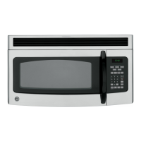
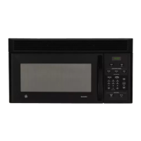
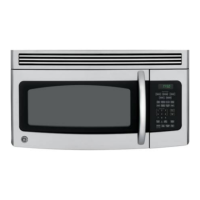
| Type | Over-the-Range |
|---|---|
| Capacity | 1.5 cu. ft. |
| Power | 1000 Watts |
| Control Type | Electronic Touch |
| Ventilation | Recirculating or External Venting |
| Color | Stainless Steel |
| Turntable | Yes |
| Ventilation Fan | Yes |
| Voltage | 120V |
| Sensor Cooking | Yes |
| Pre-Programmed Settings | Yes |
| Child Lock | Yes |
| Watts | 1000 Watts |