GE LOGIQ F SERIES
D
IRECTION 5446617-100, REVISION 10 BASIC SERVICE MANUAL
3 - 14 Section 3-6 - System Configuration
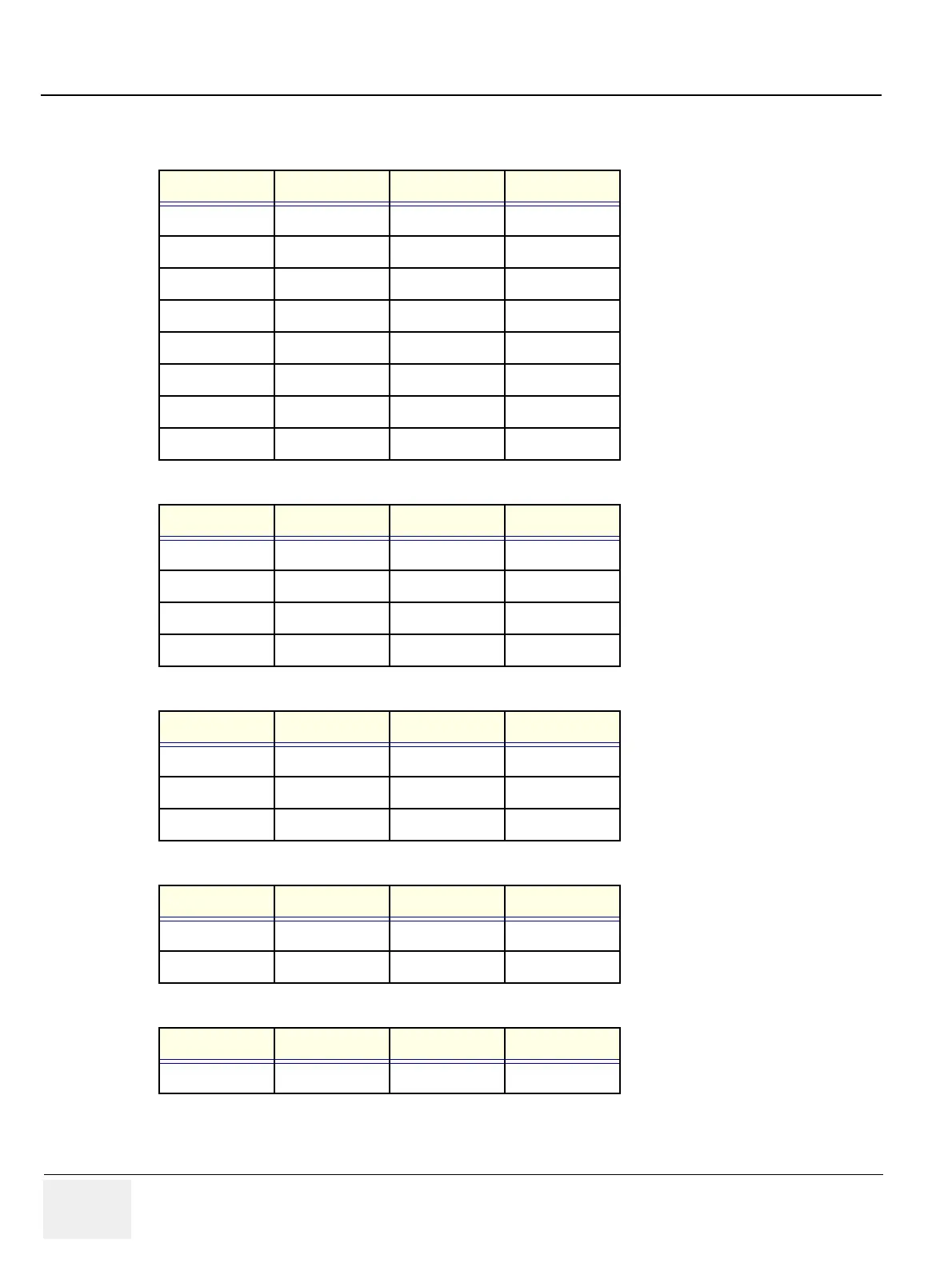
3-6-5-2 Pin assignment for each connector
Table 3-9 Pin Assignments of External VGA
Pin No. Signal Pin No. Signal
1RED9 NC
2 GREEN 10 NC
3BLUE11 NC
4NC12NC
5NC13HSY
6 GND 14 VSY
7 GND 15 NC
8GND
Table 3-10 Pin Assignments of USB
Pin No. Signal Pin No. Signal
1 +5 VDC 5 +5 VDC
2DATA6DATA
3DATA7DATA
4GND8GND
Table 3-11 Pin Assignments of Audio
Pin No. Signal Pin No. Signal
1GND4 NC
2L+5R+
3 Speaker L 6 Speaker R
Table 3-12 Pin Assignment of S-Video
Pin No. Output Signal Pin No. Output Signal
1GND3 Y
2GND4 C
Table 3-13 Pin Assignment of Composite Video Out
Pin No. Output Signal Pin No. Output Signal
1 Composite Out 2 GND
 Loading...


