2
-
2
MDP Digital Time Overcurrent Relay GE Power Management
2 OPERATING PRINCIPLES GEK-100682D
2
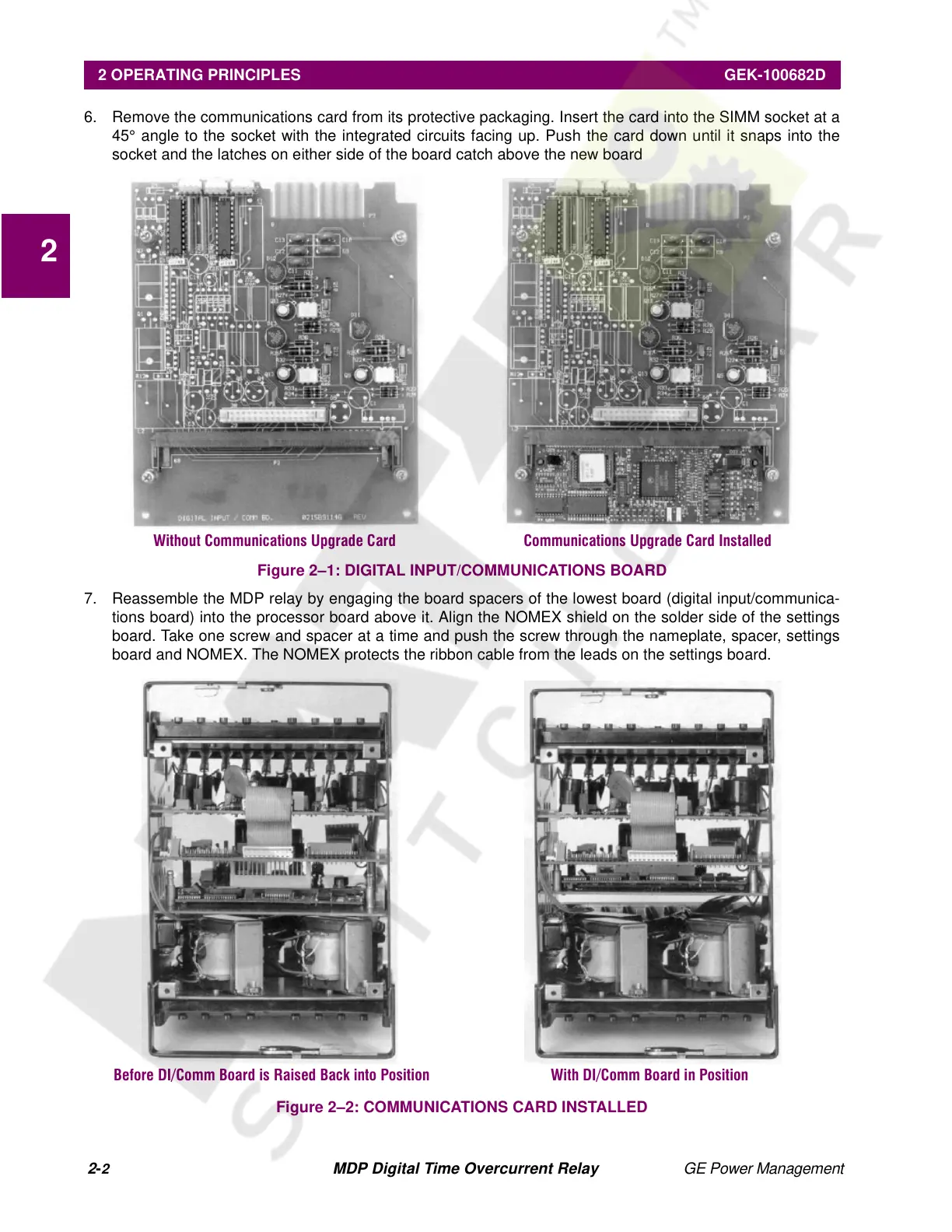
6. Remove the communications card from its protective packaging. Insert the card into the SIMM socket at a
45° angle to the socket with the integrated circuits facing up. Push the card down until it snaps into the
socket and the latches on either side of the board catch above the new board
Figure 2–1: DIGITAL INPUT/COMMUNICATIONS BOARD
7. Reassemble the MDP relay by engaging the board spacers of the lowest board (digital input/communica-
tions board) into the processor board above it. Align the NOMEX shield on the solder side of the settings
board. Take one screw and spacer at a time and push the screw through the nameplate, spacer, settings
board and NOMEX. The NOMEX protects the ribbon cable from the leads on the settings board.
Figure 2–2: COMMUNICATIONS CARD INSTALLED
Without Communications Upgrade Card Communications Upgrade Card Installed
Before DI/Comm Board is Raised Back into Position With DI/Comm Board in Position
Courtesy of NationalSwitchgear.com