Do you have a question about the GE Multilin 745 and is the answer not in the manual?
Guides through initial setup, emphasizing safety warnings and checks.
Explains menu navigation, setpoint and actual value display conventions.
Details methods for editing numerical, enumeration, and text setpoints securely.
Covers setting up and managing passcode security for setpoint changes.
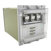
Provides a general description of the 745 relay, its features, and adaptive capabilities.
Lists the protection elements available for windings 1, 2, and 3, and common elements.
Details the various order codes for configuring the 745 Transformer Management Relay.
Describes the SR series arrangement, case dimensions, and panel cutout requirements.
Provides instructions for mounting the SR unit's case into the supporting panel.
Explains the procedure for safely removing and inserting the relay unit from its case.
Covers general aspects of interconnections for instrument transformers, inputs, outputs, and communications.
Details the front panel components: display, LEDs, keys, and RS232 port.
Introduces the enerVista 745 Setup software for configuration and monitoring.
Guides through configuring serial and Ethernet communications for software connection.
Explains how to engage a device, enter setpoints, and manage setpoint files.
Introduces the setpoint structure and grouping within the relay and software.
Details how the relay automatically corrects for CT ratio, phase shifts, and zero-sequence components.
Covers setpoints for passcode, preferences, communications, resetting, clock, and default messages.
Configures transformer characteristics, winding data, tap changer, harmonics, and voltage inputs.
Details configuration for logic and virtual inputs, used for custom schemes and FlexLogic.
Covers configuration of protection and monitoring elements like differential, overcurrent, and frequency.
Explains the configuration of digital and analog outputs using FlexLogic equations.
Provides tools for verifying relay functionality through output testing and simulation.
Introduces accessing measured values, event records, and product information.
Displays date, time, logic input/output states, and self-test errors.
Shows current, harmonic content, frequency, voltage, demand, and power measurements.
Provides access to event data, clearing functions, and detailed event records.
Contains technical support contact, revision codes, calibration dates, and target/flash messages.
Outlines safety precautions, test equipment, and general preliminary work before testing.
Covers initial steps for relay verification, including connections, settings, and basic checks.
Details testing procedures for digital inputs and output relays, including manual control.
Verifies AC current and voltage inputs, harmonic content, and transformer parameters.
Tests various protection elements like differential, overcurrent, frequency, and insulation aging.
Lists revision history and major updates to the 745 Manual.
Declares conformity to relevant EU directives and standards for electrical equipment.
Outlines the warranty terms, conditions, and limitations for GE Multilin products.
| Model | 745 |
|---|---|
| Current Rating | Up to 5 A |
| Frequency | 50/60 Hz |
| Frequency Range | 45-65 Hz |
| Digital Inputs | 8 |
| Number of Binary Inputs | 8 |
| Number of Analog Inputs | 4 |
| Display | LCD |
| Manufacturer | GE |
| Input Voltage | 57 - 300 V AC/DC |
| Communication Protocols | DNP 3.0, Modbus |
| Protection Functions | Overcurrent, Overvoltage, Undervoltage, Frequency, Breaker Failure |
| Metering | Voltage, Current, Power, Energy, Frequency |
| Mounting | Panel |
| Operating Temperature | -20° to +70°C |
| Enclosure Rating | IP54 |


 Loading...