S4 Elements745
Transformer Management Relay
Setpoints
http://www.GEindustrial.com/multilin
5–82
GE Multilin
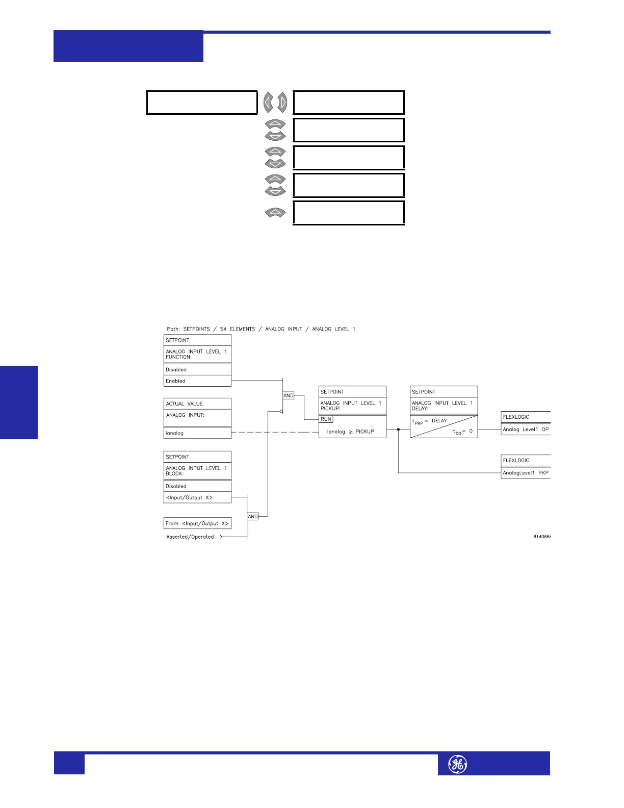
Analog Input Level PATH: SETPOINTS !" S4 ELEMENTS !" ANALOG INPUT ! ANALOG LEVEL 1(2)
The 745 can monitor any external quantity, such as bus voltage, battery voltage,
etc., via a general purpose auxiliary current input called the analog input. Any one
of the standard transducer output ranges 0-1 mA, 0-5 mA, 4-20 mA, or 0-20 mA
can be connected to the analog input terminals. The analog input is configured in
S2
SYSTEM SETUP !" ANALOG INPUT and the actual values displayed in A2 METERING
!"ANALOG INPUT.
FIGURE 5–42: Analog Level Scheme Logic
! ANALOG LEVEL 1 [!] ANALOG INPUT LEVEL 1
FUNCTION: Disabled
Range: Enabled, Disabled
MESSAGE
ANALOG INPUT LEVEL 1
TARGET: Self-Reset
Range: Self-Reset, Latched, None
MESSAGE
ANALOG INPUT LEVEL 1
PICKUP: 10
µA
Range: 1 to 65000 µA in steps of 1
MESSAGE
ANALOG INPUT LEVEL 1
DELAY: 50 s
Range: 0 to 60000 s in steps of 1
MESSAGE
ANALOG INPUT LEVEL 1
BLOCK: Disabled
Range: Logc Inpt 1 to 16, Virt Inpt 1 to
16, Output Rly 2 to 8, SelfTest
Rly, Vir Outpt 1 to 5, Disabled