S4 Elements
745
Transformer Management Relay
Setpoints
http://www.GEindustrial.com/multilin
5–71
GE Multilin
Overexcitation a) Main Menu
PATH: SETPOINTS !" S4 ELEMENTS !" OVEREXCITATION
A transformer is designed to operate at or below a maximum magnetic flux density
in the transformer core. Above this design limit the eddy currents in the core and
nearby conductive components cause overheating which within a very short time
may cause severe damage. The magnetic flux in the core is proportional to the
voltage applied to the winding divided by the impedance of the winding. The flux in
the core increases with either increasing voltage or decreasing frequency. During
startup or shutdown of generator-connected transformers, or following a load
rejection, the transformer may experience an excessive ratio of volts to hertz, that
is, become overexcited.
When a transformer core is overexcited, the core is operating in a non-linear
magnetic region, and creates harmonic components in the exciting current. A
significant amount of current at the 5th harmonic is characteristic of overexcitation.
This section contains the settings to configure the overexcitation monitoring
elements. Included are a 5th harmonic level, and two volts-per-hertz elements,
each with a pickup level and a time delay.
b) 5TH Harmonic Level
PATH: SETPOINTS !" S4 ELEMENTS !" OVEREXCITATION ! 5TH HARMONIC LEVEL
• MINIMUM OPERATING CURRENT: Enter the minimum value of current (in
units of relay nominal current) required to allow the 5th harmonic level element
to operate.
• 5TH HARMONIC LEVEL PICKUP: Enter the 5th harmonic current (in %ƒ
0
)
above which the 5th harmonic level element will pickup and start the delay
timer.
• 5TH HARMONIC LEVEL DELAY: Enter the time that the 5th harmonic current
must remain above the pickup level before the element operates.
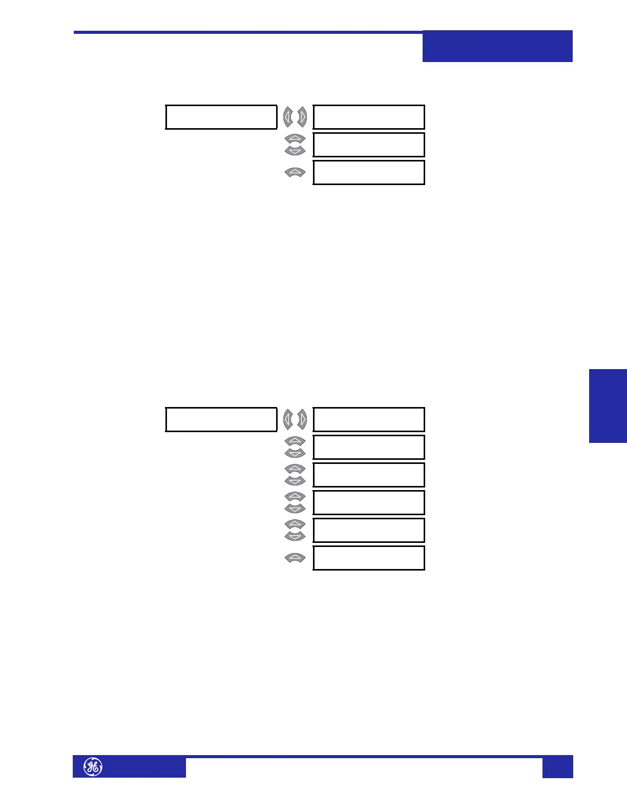
! OVEREXCITATION [!] ! 5th HARMONIC [!]
LEVEL
See page 5–71.
MESSAGE
! VOLTS PER [!]
HERTZ 1
See page 5–72.
MESSAGE
! VOLTS PER [!]
HERTZ 2
See page 5–72.
! 5th HARMONIC [!]
LEVEL
5th HARMONIC LEVEL
FUNCTION: Disabled
Range: Enabled, Disabled
MESSAGE
5th HARMONIC LEVEL
TARGET: Self-Reset
Range: Self-Reset, Latched, None
MESSAGE
MINIMUM OPERATING
CURRENT: 0.10 x CT
Range: 0.03 to 1.00 x CT in steps of
0.01
MESSAGE
5th HARMONIC LEVEL
PICKUP: 10.0% fo
Range: 0.1 to 99.9% f
0
in steps of 0.1
MESSAGE
5th HARMONIC LEVEL
DELAY: 10 s
Range: 0 to 60000 s in steps of 1
MESSAGE
5th HARMONIC LEVEL
BLOCK: Disabled
Range: Logc Inpt 1 to 16, Virt Inpt 1 to
16, Output Rly 2 to 8, SelfTest
Rly, Vir Outpt 1 to 5, Disabled