S4 Elements745
Transformer Management Relay
Setpoints
http://www.GEindustrial.com/multilin
5–56
GE Multilin
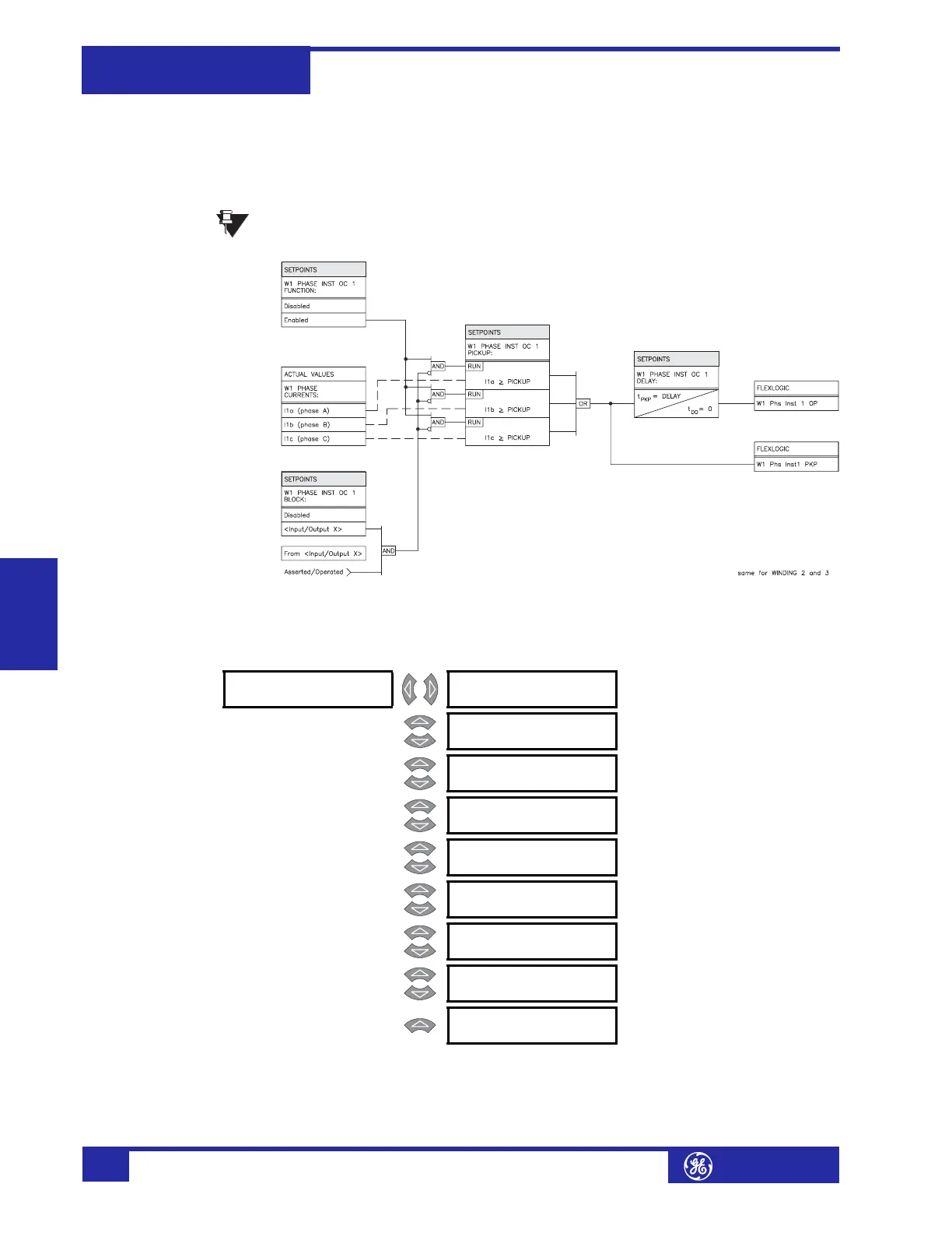
• W1(3) PHASE INST OC 1(2) PICKUP: Enter the level of phase current (in
units of relay nominal current) above which the Winding 1(3) Phase
Instantaneous Overcurrent 1 element will pickup and start the delay timer.
• W1(3) PHASE INST OC 1(2) DELAY: Enter the time that the phase current
must remain above the pickup level before the element operates.
The setpoint messages above and the following logic diagram are identical
for the Phase Instantaneous Overcurrent 2 element.
FIGURE 5–16: Phase Instantaneous Overcurrent 1 Scheme Logic
Neutral Overcurrent a) Main Menu
PATH: SETPOINTS !" S4 ELEMENTS !" NEUTRAL OC
In the 745, “neutral” refers to residual current (3I
0
), calculated internally as the
vector sum of the three phases. The relay includes neutral time overcurrent and two
levels of neutral instantaneous overcurrent for each winding.
NOTE
! NEUTRAL OC [!] ! W1 NTRL [!]
TIME OC
See page 5–57.
MESSAGE
! W2 NTRL [!]
TIME OC
See page 5–57.
MESSAGE
! W3 NTRL [!]
TIME OC
See page 5–57.
MESSAGE
! W1 NTRL [!]
INST OC 1
See page 5–58.
MESSAGE
! W2 NTRL [!]
INST OC 1
See page 5–58.
MESSAGE
! W3 NTRL [!]
INST OC 1
See page 5–58.
MESSAGE
! W1 NTRL [!]
INST OC 2
See page 5–58.
MESSAGE
! W2 NTRL [!]
INST OC 2
See page 5–58.
MESSAGE
! W3 NTRL [!]
INST OC 2
See page 5–58.