S5 Outputs745
Transformer Management Relay
Setpoints
http://www.GEindustrial.com/multilin
5–88
GE Multilin
This ordering of parameters of an equation, where the gate (or “operator”) follows
the input (or “value”) is commonly referred to as “Postfix” or “Reverse Polish”
notation.
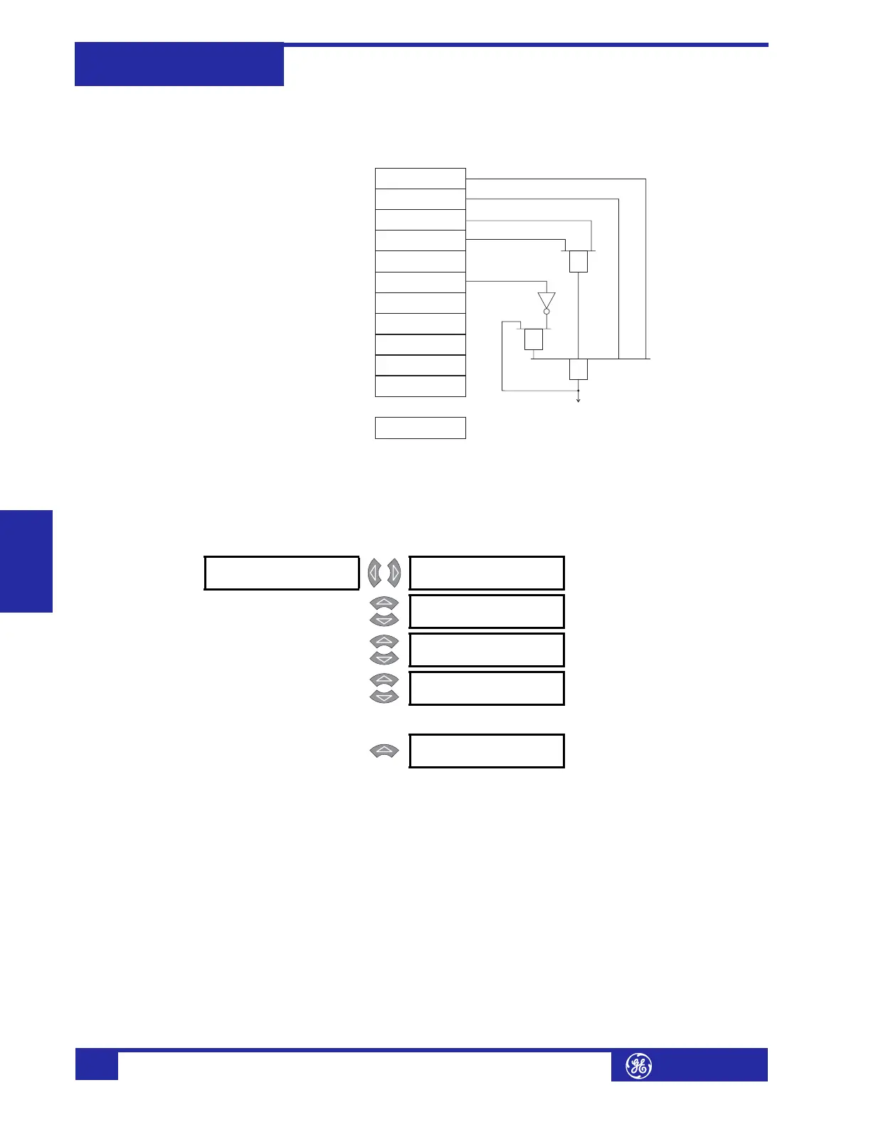
FIGURE 5–47: FlexLogic™ Example Implemented
Any equation entered in the 745 that does not make logical sense according to the
notation described here, will be flagged as a self-test error. The
SELF TEST ERROR:
FlexLogic Eqn
message will be displayed until the error is corrected.
Output Relays PATH: SETPOINTS !" S5 OUTPUTS ! OUTPUT RELAYS ! OUTPUT RELAY 1(8)
This section contains the settings (including the FlexLogic™ equation) to configure
output relays 1 to 8.
• OUTPUT 1(8) NAME: Press ENTER edit the name of the output. The text may be
changed from
Solid State Trip one character at a time, using the VA L U E keys.
Press ENTER to store the edit and advance to the next character position.
• OUTPUT 1(8) OPERATION: Select “Latched” to maintain the Output 1(8)
contacts in the energized state, even after the condition that caused the
contacts to operate is cleared, until a reset command is issued (or automatically
after one week). Select “Self-reset” to automatically de-energize the contacts
after the condition is cleared. The solid state output (Output 1) remains closed
until externally reset by a momentary interruption of current, unless wired in
parallel with an electromechanical relay (Outputs 2 to 8) in which case it turns
off when the relay operates.
• OUTPUT 1(8) TYPE: Select “Trip” to turn the Trip LED on or “Alarm” to turn
the Alarm LED on when this output operates. Otherwise, select “Control”. Note
OUTPUT 2 FLEXLOGIC
O1: Percent Diff OP
OUTPUT 2 FLEXLOGIC
O2: Inst Diff OP
OUTPUT 2 FLEXLOGIC
O3: Virtual Output 1
OUTPUT 2 FLEXLOGIC
O4: Logic Input 1
OUTPUT 2 FLEXLOGIC
O7: NOT
OUTPUT 2 FLEXLOGIC
O5: XOR (2 inputs)
XOR
AND
OR
OUTPUT 2 FLEXLOGIC
O8: Output Relay 2
OUTPUT 2 FLEXLOGIC
O6: Logic Input 2
OUTPUT 2 FLEXLOGIC
O9: AND (2 inputs)
OUTPUT 2 FLEXLOGIC
11: END
Output Relay 2
OPERATE
OUTPUT 2 FLEXLOGIC
1O: OR (4 inputs)
OUTPUT 2 FLEXLOGIC
20: END
...
! OUTPUT RELAY 1 [!] OUTPUT 1 NAME:
Solid State Trip
Range: Enabled, Disabled
MESSAGE
OUTPUT 1 OPERATION:
Self-Resetting
Range: Self-Resetting, Latched
MESSAGE
OUTPUT 1 TYPE:
Trip
Range: Trip, Alarm, Control
MESSAGE
OUTPUT 1 FLEXLOGIC
01: Percent Diff Op
Range: any FlexLogic™ input or gate
↓
MESSAGE
OUTPUT 1 FLEXLOGIC
20: END
Range: any FlexLogic™ input or gate