Auto-Configuration
745
Transformer Management Relay
Setpoints
http://www.GEindustrial.com/multilin
5–9
GE Multilin
Phase Angle
Correction
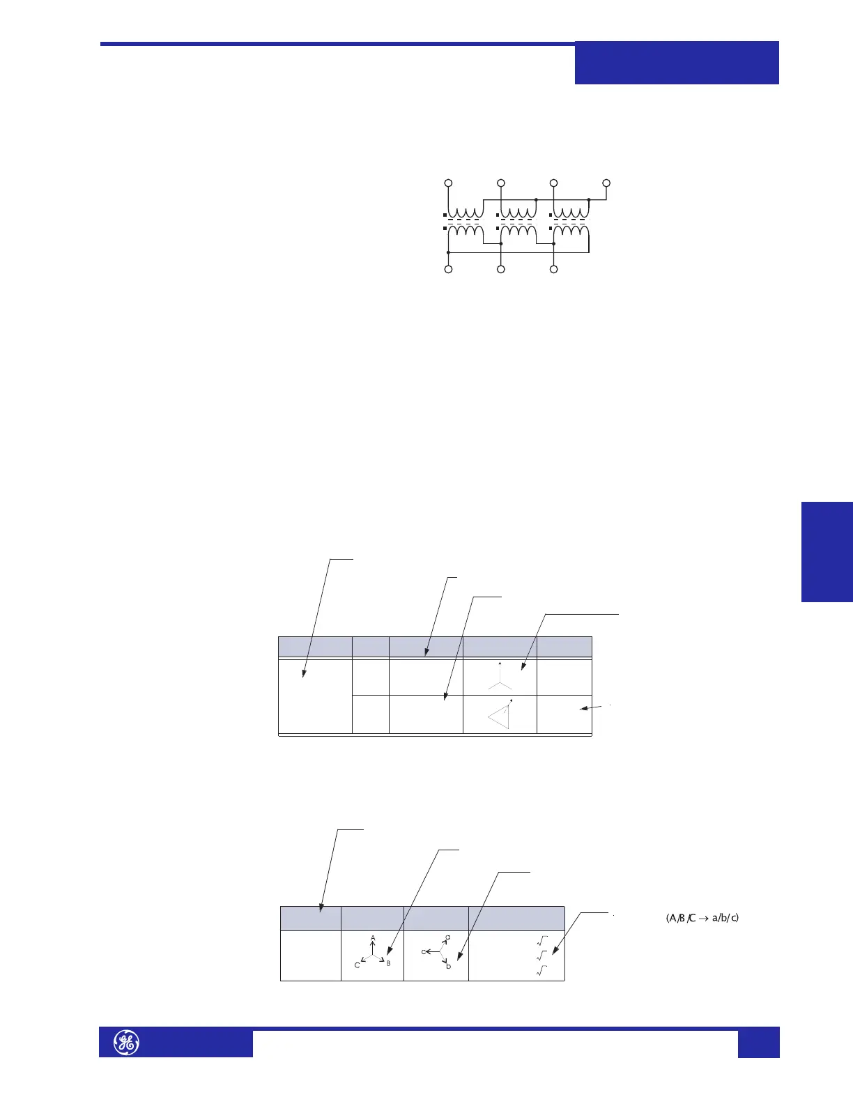
The following diagram shows the internal connections of the Y/d30° transformer of
our example:
FIGURE 5–5: Wye / Delta (30° Lag) Transformer
Under balanced conditions, the Winding 2 phase current phasors lag the
corresponding phase current phasors of Winding 1 by 30°. With CTs connected in a
Wye arrangement (polarity markings pointing away from the transformer), the
corresponding phase currents cannot be summed directly to obtain a zero
differential current, since corresponding phasors will NOT be 180° out-of-phase.
Traditionally, this problem is solved by connecting the CTs on the WYE side of the
transformer (Winding 1) in a Delta arrangement. This compensates for the phase
angle lag introduced in the Delta side (Winding 2).
The 745 performs this phase angle correction internally based on the following
setpoint. Set
S2 SYSTEM SETUP ! TRANSFORMER !" TRANSFORMER TYPE to “Y/d30°”.
The 745 supports over 100 two and three-winding transformer types. Table 5–1:
Transformer Types on page 5–11 provides the following information about each
transformer type:
As shown in the “Y/d30°” entry of the table of transformer types, the phase angle
correction (or phase shift) introduces 30° lag in Winding 1. This lag is described in
Table 5–2: Phase Shifts on page 5–23. This table provides the following information
about each phase shift type:
WINDING 1 (WYE)
WINDING 2 (DELTA)
abc
AB
C
N
TRANS FOR ME R
TYP E
WDG
#
CONNE CTION VOLTA GE
PHASORS
PHASE
SHIFT
Y/d30°
1
WYE
(gnd1/2)
30° la g
2DELTA
30° la g
0°
angle by which a winding lags W inding 1
winding connection (wye, delta, or zig-zag) and ground C T assignment
transformer type notation as it appears on the display
diagrams showing the phase rela-
t ionship of voltage phasors, where
+ (the arrow head) indicates the
reference phase
phase angle correction (or phase shift )
that is performed internally to calculate
diff erential currents
PHASE
SHIFT
INPUT
PHASORS
OUTPUT
PHASORS
PHASOR
TRANS FORMATION
30° lag
a=(A–C)/
b=(B – A)/
c=(C–B)/
3
3
3
the phase shift a s it appears in the table of tra nsformer types
the phasors before the phase shift is applied (A/B /C)
the phasors aft er the phase shift is applies (a/b/c)
the equations used to achieve the
phase shift