Auto-Configuration
745
Transformer Management Relay
Setpoints
http://www.GEindustrial.com/multilin
5–23
GE Multilin
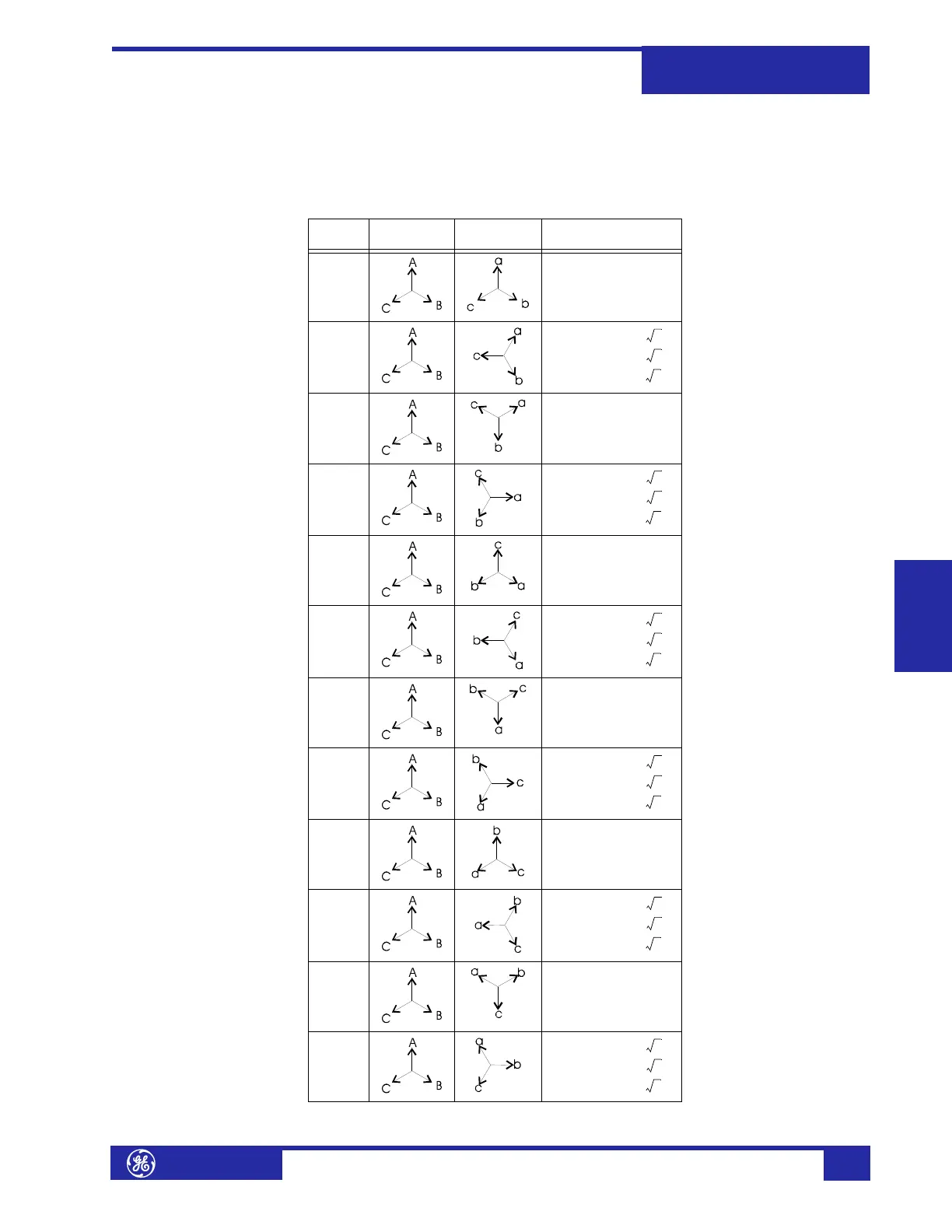
Phase Shifts The table below provides additional information about the Phase Shift column in
Table 5–1: Transformer Types on page 5–11 and represents an assumed ABC phasor
rotation. For transformers connected to a system with a phasor rotation of ACB,
interchange all B (b) and C (c) designations.
Table 5–2: Phase Shifts
Phase
Shift
Input
Phasors
Output
Phasors
Phasor
Transformation
0° a = A
b = B
c = C
30° lag
a = (A – C) /
b = (B – A) /
c = (C – B) /
60° lag a = –C
b = –A
c = –B
90° lag
a = (B – C) /
b = (C – A) /
c = (A – B) /
120°
lag
a = B
b = C
c = A
150°
lag
a = (B – A) /
b = (C – B) /
c = (A – C) /
180°
lag
a = –A
b = –B
c = –C
210°
lag
a = (C – A) /
b = (A – B) /
c = (B – C) /
240°
lag
a = C
b = A
c = B
270°
lag
a = (C – B) /
b = (A – C) /
c = (B – A) /
300°
lag
a = –B
b = –C
c = –A
330°
lag
a = (A – B) /
b = (B – C) /
c = (C – A) /
3
3
3
3
3
3
3
3
3
3
3
3
3
3
3
3
3
3