S5 Outputs745
Transformer Management Relay
Setpoints
http://www.GEindustrial.com/multilin
5–86
GE Multilin
S5 Outputs
Description The S5 OUTPUTS page contains the settings to configure all outputs. The 745 has
nine digital outputs (one solid-state, four trip rated form A contacts, and four
auxiliary form C contacts) which are fully programmable using FlexLogic™
equations. FlexLogic™ is a highly flexible and easy-to-use equation format which
allows any combination of protection and monitoring elements, logic inputs,
outputs, and timers to be assigned to any output, using multiple input AND, OR,
NAND, NOR, XOR, and NOT Boolean logic gates. Each digital output can have an
equation of up to 20 parameters. Five “virtual outputs” are also available, each
having an equation containing up to 10 parameters, whose output can be used as a
parameter in any other equation.
In addition to these outputs, the conditions to trigger a waveform capture (trace
memory) is also programmable using FlexLogic™. A 10 parameter equation is
provided for this purpose.
Introduction to
FlexLogic™
A FlexLogic™ equation defines the combination of inputs and logic gates to operate
an output. Each output has its own equation, an equation being a linear array of
parameters. Evaluation of an equation results in either a 1 (= ON, i.e. operate the
output), or 0 (= OFF, i.e. do not operate the output).
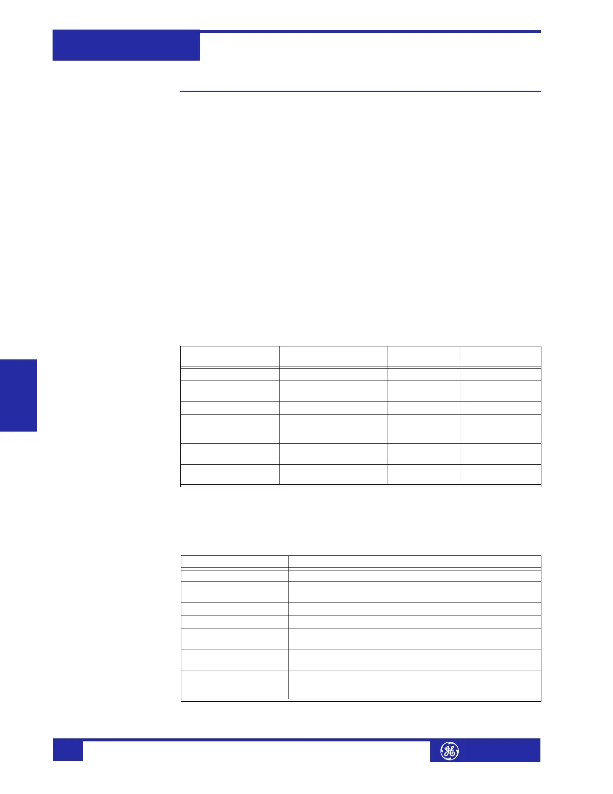
The table below provides information about FlexLogic™ equations for all outputs:
As mentioned above, the parameters of an equation can contain either INPUTS or
GATES.
Table 5–10: FlexLogic™ Output Types
Name Type Equation
Parameters
Evaluation Rate
Output Relay 1 solid-state 20 every 1/2 cycle*
Output Relays 2 to 5 trip-rated form A
contacts
20 each every 1/2 cycle*
Output Relays 6 to 8 form C contacts 20 each every 100 ms
Self-Test Relay form C contacts
dedicated for self-test
(not programmable)
--- every 100 ms
Trace Trigger waveform capture
trigger
10 every 1/2 cycle*
Virtual Outputs internal register (for use
in other equations)
10 each every 1/2 cycle*
* refers to the power system cycle as detected by the frequency circuitry of the 745.
Table 5–11: FlexLogic™ Input Types
Inputs Input is “1” (= ON) if...
Element* pickup The pickup setting of the element is exceeded
Element* operate The pickup setting of the element is exceeded for the
programmed time delay
Logic Inputs 1 to 16 The logic input contact is asserted
Virtual Inputs 1 to 16 The virtual input is asserted
Output Relays 1 to 8 The output relay operates
(i.e. evaluation of the FlexLogic™ equation results in a ‘1’)
Virtual Outputs 1 to 5 The virtual output operates
(i.e. evaluation of the FlexLogic™ equation results in a ‘1’)
Timers 1 to 10 The timer runs to completion
(i.e. the ‘start’ condition is met for the programmed time
delay)
* refers to any protection or monitoring element in page
S4 ELEMENTS.