S6 Testing
745
Transformer Management Relay
Setpoints
http://www.GEindustrial.com/multilin
5–91
GE Multilin
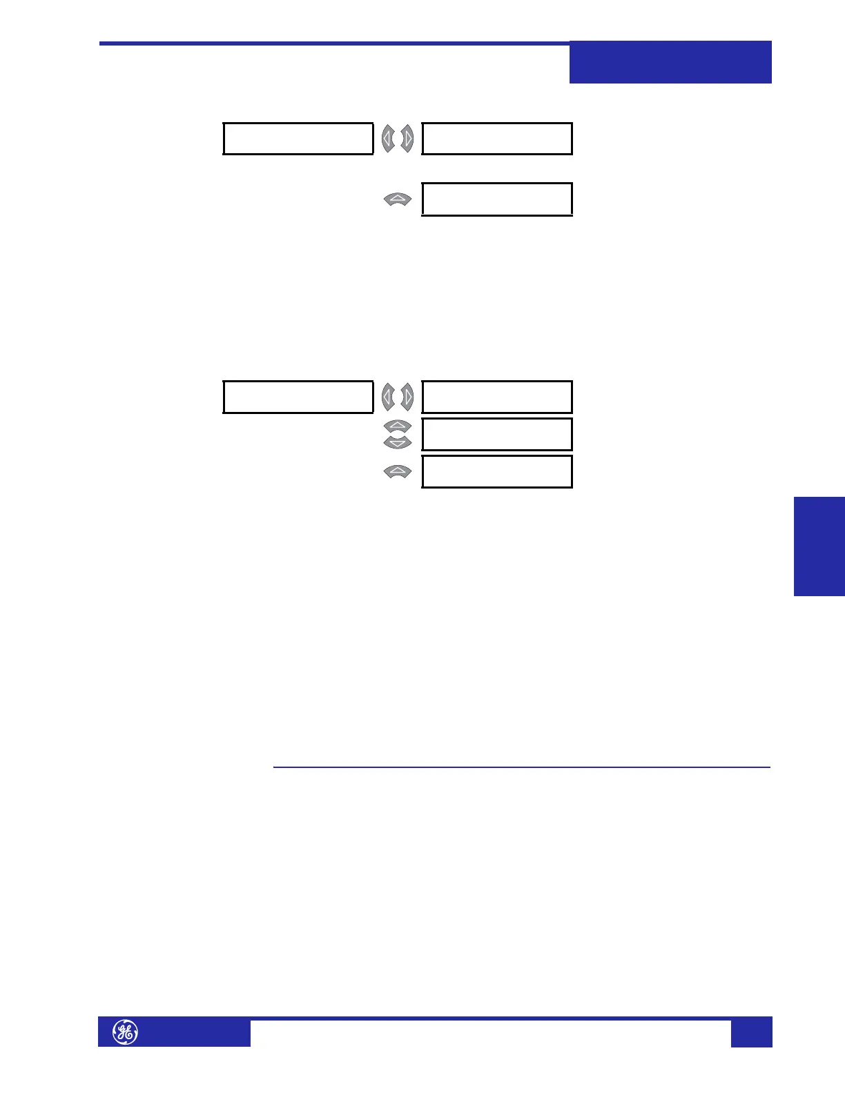
Virtual Outputs PATH: SETPOINTS !" S5 OUTPUTS !" TRACE MEMORY
Virtual outputs are FlexLogic™ equations whose output (or result) can be used as
inputs to other equations. The 745 has five (5) virtual outputs. One application of
these outputs may be to contain a block of logic that is repeated for more than one
output.
This section contains the FlexLogic™ equations to configure Virtual Outputs 1 to 5.
The setpoints describe the parameters of the FlexLogic™ equation for Virtual Output
1(5) as described in the introduction to FlexLogic™.
Timers PATH: SETPOINTS !" S5 OUTPUTS !" TIMERS ! TIMER 1(10)
Protection and monitoring elements already have their own programmable delay
timers, where they are required. For additional flexibility, ten (10) independent
timers are available for implementing custom schemes where timers are not
available. For example, a pickup delay timer may be required on a logic input; or, a
single delay timer may be required on the output of a block of logic.
• TIMER 1(10) START: Select the FlexLogic™ entry which, when operated or
asserted, will start Timer 1(10).
• TIMER 1(10) PICKUP DELAY: Enter the delay time during which the start
condition for Timer 1(10) must remain operated or asserted, before the timer
will operate.
• TIMER 1(10) DROPOUT DELAY: Enter the delay time after which the start
condition for Timer 1(10) must remain not operated or not asserted, before the
timer will stop operating.
S6 Testing
Description The 745 provides various diagnostic tools to verify the relay functionality. The
normal function of all output contacts can be overridden and forced to be energized
or de-energized. Analog outputs may be forced to any level of their output range.
The simulation feature allows system parameters (magnitudes and angles) to be
entered as setpoints and made to generate fault conditions without the necessity of
any system connections. In addition, 16 cycles of sampled current/voltage
waveform data (in IEEE Comtrade file format) can be loaded and “played back” to
test the response of the 745 under any (previously recorded) system disturbance.
! VIRTUAL [!]
OUTPUT 1
VIRTUAL 1 FLEXLOGIC
01: END
Range: any FlexLogic™ input or gate
↓
MESSAGE
VIRTUAL 1 FLEXLOGIC
10: END
Range: any FlexLogic™ input or gate
! TIMER 1 [!] TIMER 1 START:
END
Range: Enabled, Disabled
MESSAGE
TIMER 1 PICKUP
DELAY: 0.00 s
Range: Self-Resetting, Latched
MESSAGE
TIMER 1 DROPOUT
DELAY: 0.00 s
Range: Trip, Alarm, Control