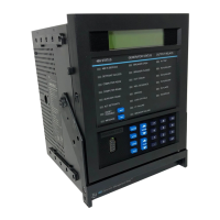
Do you have a question about the GE Multilin 489 and is the answer not in the manual?
Guidelines for initial setup, warnings, and inspection checklist for the relay.
Navigating the relay's menu structure, understanding display messages, and accessing information.
Explains how to modify setpoints, including hardware and passcode security features.
Procedures for placing the relay in service and testing it, including website resources.
Describes the 489 Generator Management Relay's features and capabilities.
Details electrical and physical specifications of the relay, including inputs, outputs, and testing standards.
Covers physical mounting of the relay case and unit, including dimensions and product identification.
Details wiring considerations for current, voltage, digital, analog inputs/outputs, and communications.
Explains the relay's front panel display, LED indicators, and keypad for navigation.
Overview of the EnerVista software for configuration, monitoring, and maintenance of the relay.
Procedures for configuring serial and Ethernet communications for relay setup.
Guidance on entering, saving, and managing setpoint files using the EnerVista software.
Steps for updating the relay's firmware, including saving and loading setpoints.
Covers advanced features like event recording, waveform capture, trending, and phasor analysis.
Describes how to use EnerVista Viewpoint for data overview and analysis.
Introduces the concept of setpoints and their organization into pages and sub-pages.
Details setpoints related to relay setup, including passcode, preferences, and communications.
Covers setpoints for current sensing, voltage sensing, and generator parameters.
Configuration options for digital inputs, including breaker status and general inputs.
Details setpoints for configuring output relays and their reset modes.
Discusses setpoints for overcurrent, negative sequence, ground overcurrent, phase differential, and directional elements.
Covers setpoints for undervoltage, overvoltage, volts/hertz, phase reversal, underfrequency, and overfrequency.
Details setpoints for reactive power, reverse power, and low forward power measurements.
Configuration options for RTD types, individual RTD settings, and short/low temperature detection.
Explains the thermal model setup, including overload curves, cooling constants, and RTD biasing.
Covers setpoints for trip counters, breaker failure, trip coil monitor, VT fuse failure, demand, and pulse output.
Configuration for analog inputs and outputs, including scaling and parameter assignment.
Details simulation modes, pre-fault setup, fault setup, and output relay testing procedures.
Introduces actual values, their access methods, and organization into logical groups.
Displays network status, generator status, last trip data, alarm status, and trip/alarm pickups.
Provides actual values for current, voltage, power, temperature, demand, and analog inputs.
Shows parameter averages, RTD maximums, and analog input minimum/maximum values.
Displays trip counters, general counters, and timers for maintenance tracking.
Accesses stored event records for troubleshooting and analysis.
Provides model, serial number, revision, and calibration information for the relay.
Explains diagnostic messages and flash messages for status indication and user guidance.
Outlines procedures for performing a complete functional test of the relay hardware and firmware.
Details tests for accuracy of output current, phase voltage, and differential/neutral current inputs.
Covers testing for overload curves, power measurement, reactive power, and voltage phase reversal.
Describes general protection concepts and guidelines for protecting a generator stator against ground faults.
Discusses the application of two 489 relays for dual-breaker generator configuration and stator differential logic.
Provides information on ground fault CTs and phase CTs, including dimensions and specifications.
Displays ANSI, IEC, and IAC time overcurrent curves for protection coordination.
Lists changes and updates made to the manual across different revisions.
Official declaration regarding compliance with EU directives for the equipment.
Outlines the warranty terms and conditions for GE Multilin relays.


 Loading...