CHAPTER 7: TESTING
489 GENERATOR MANAGEMENT RELAY – INSTRUCTION MANUAL 7–21
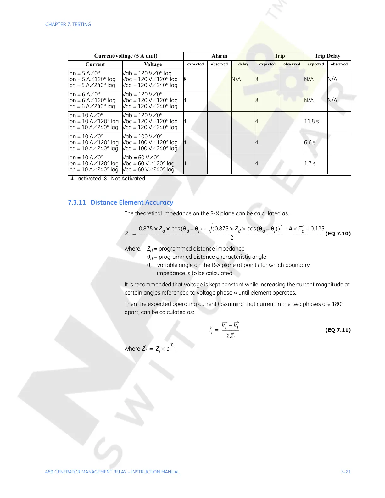
7.3.11 Distance Element Accuracy
The theoretical impedance on the R-X plane can be calculated as:
(EQ 7.10)
where: Z
d
= programmed distance impedance
θ
d
= programmed distance characteristic angle
θ
i
= variable angle on the R-X plane at point i for which boundary
impedance is to be calculated
It is recommended that voltage is kept constant while increasing the current magnitude at
certain angles referenced to voltage phase A until element operates.
Then the expected operating current (assuming that current in the two phases are 180°
apart) can be calculated as:
(EQ 7.11)
where .
Current/voltage (5 A unit) Alarm Trip Trip Delay
Current Voltage
expected observed delay expected observed expected observed
Ian = 5 A∠0°
Ibn = 5 A∠120° lag
Icn = 5 A∠240° lag
Vab = 120 V∠0° lag
Vbc = 120 V∠120° lag
Vca = 120 V∠240° lag
8 N/A 8 N/A N/A
Ian = 6 A∠0°
Ibn = 6 A∠120° lag
Icn = 6 A∠240° lag
Vab = 120 V∠0°
Vbc = 120 V∠120° lag
Vca = 120 V∠240° lag
48N/A N/A
Ian = 10 A∠0°
Ibn = 10 A∠120° lag
Icn = 10 A∠240° lag
Vab = 120 V∠0°
Vbc = 120 V∠120° lag
Vca = 120 V∠240° lag
4411.8 s
Ian = 10 A∠0°
Ibn = 10 A∠120°
lag
Icn = 10 A∠240° lag
Vab = 100 V∠0°
Vbc = 100 V∠120° lag
Vca = 100 V∠240° lag
446.6 s
Ian = 10 A∠0°
Ibn = 10 A∠120° lag
Icn = 10 A∠240° lag
Vab = 60 V∠0°
Vbc = 60 V∠120° lag
Vca = 60 V∠240° lag
441.7 s
4 activated; 8 Not Activated
Z
i
0.875 Z
d
θ
d
θ
i
–()cos×× 0.875 Z
d
θ
d
θ
i
–()cos××()
2
4 Z
d
2
0.125××++
2
------------------------------------------------------------------------------------------------------------------------------------------------------------------------------------------=
I
i
V
a
V
b
–
2Z
i
-----------------=
Courtesy of NationalSwitchgear.com