489 GENERATOR MANAGEMENT RELAY – INSTRUCTION MANUAL 3–1
489 Generator Management Relay
Chapter 3: Installation
Digital Energy
Multilin
Instal lation
3.1 Mechanical Installation
3.1.1 Description
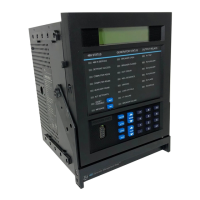
The 489 is packaged in the standard GE Multilin SR-series arrangement, which consists of
a drawout unit and a companion fixed case. The case provides mechanical protection to
the unit, and is used to make permanent connections to all external equipment. The only
electrical components mounted in the case are those required to connect the unit to the
external wiring. Connections in the case are fitted with mechanisms required to allow the
safe removal of the relay unit from an energized panel, such as automatic CT shorting. The
unit is mechanically held in the case by pins on the locking handle, which cannot be fully
lowered to the locked position until the electrical connections are completely mated. Any
489 can be installed in any 489 case, except for custom manufactured units that are
clearly identified as such on both case and unit, and are equipped with an index pin keying
mechanism to prevent incorrect pairings.
No special ventilation requirements need to be observed during the installation of the unit,
but the unit should be wiped clean with a damp cloth.
Courtesy of NationalSwitchgear.com
 Loading...


