3–10 489 GENERATOR MANAGEMENT RELAY – INSTRUCTION MANUAL
CHAPTER 3: INSTALLATION
FIGURE 3–10: Typical Wiring Diagram
3.2.2 General Wiring Considerations
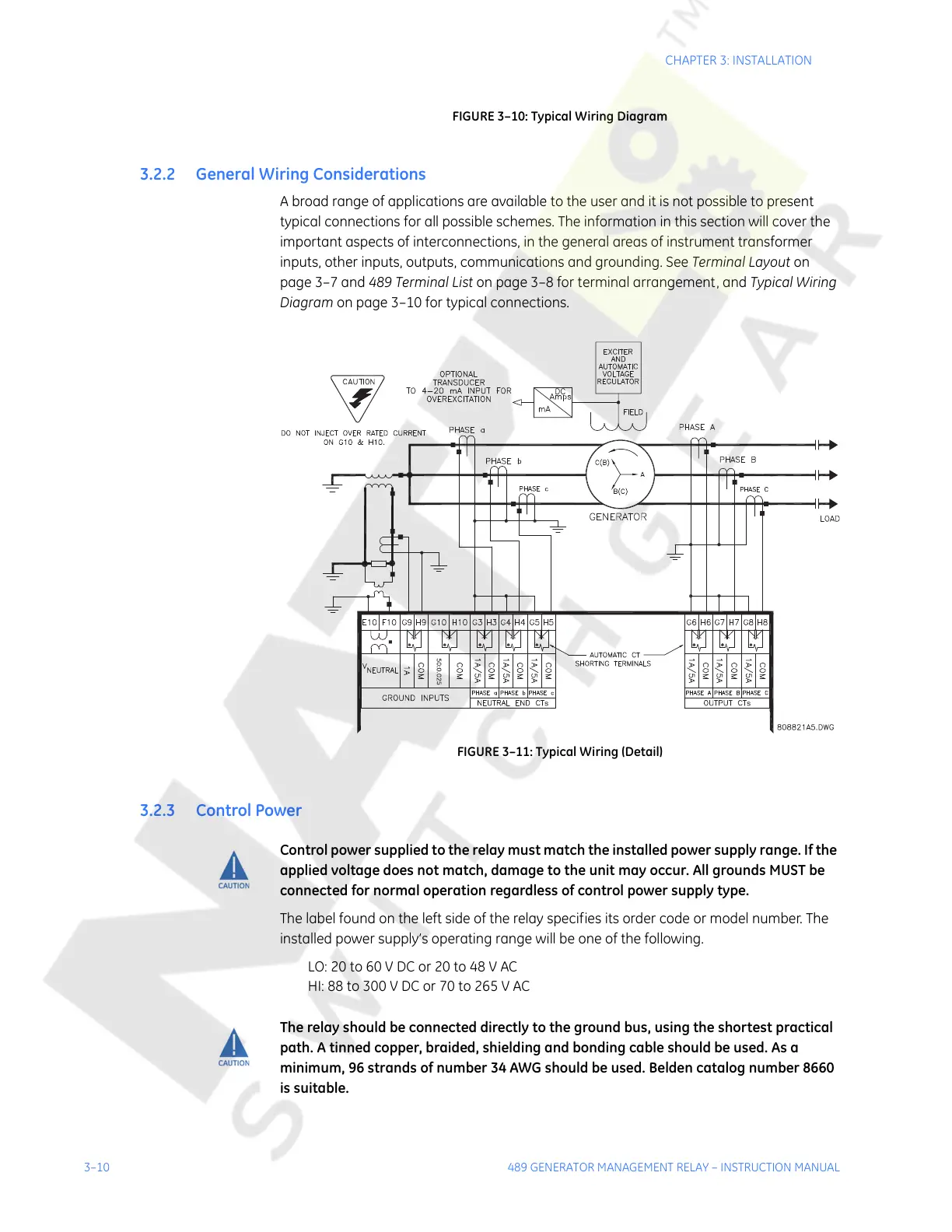
A broad range of applications are available to the user and it is not possible to present
typical connections for all possible schemes. The information in this section will cover the
important aspects of interconnections, in the general areas of instrument transformer
inputs, other inputs, outputs, communications and grounding. See Terminal Layout on
page 3–7 and 489 Terminal List on page 3–8 for terminal arrangement, and Typical Wiring
Diagram on page 3–10 for typical connections.
FIGURE 3–11: Typical Wiring (Detail)
3.2.3 Control Power
Control power supplied to the relay must match the installed power supply range. If the
applied voltage does not match, damage to the unit may occur. All grounds MUST be
connected for normal operation regardless of control power supply type.
The label found on the left side of the relay specifies its order code or model number. The
installed power supply’s operating range will be one of the following.
LO: 20 to 60 V DC or 20 to 48 V AC
HI: 88 to 300 V DC or 70 to 265 V AC
The relay should be connected directly to the ground bus, using the shortest practical
path. A tinned copper, braided, shielding and bonding cable should be used. As a
minimum, 96 strands of number 34 AWG should be used. Belden catalog number 8660
is suitable.
Courtesy of NationalSwitchgear.com