2–4 489 GENERATOR MANAGEMENT RELAY – INSTRUCTION MANUAL
CHAPTER 2: INTRODUCTION
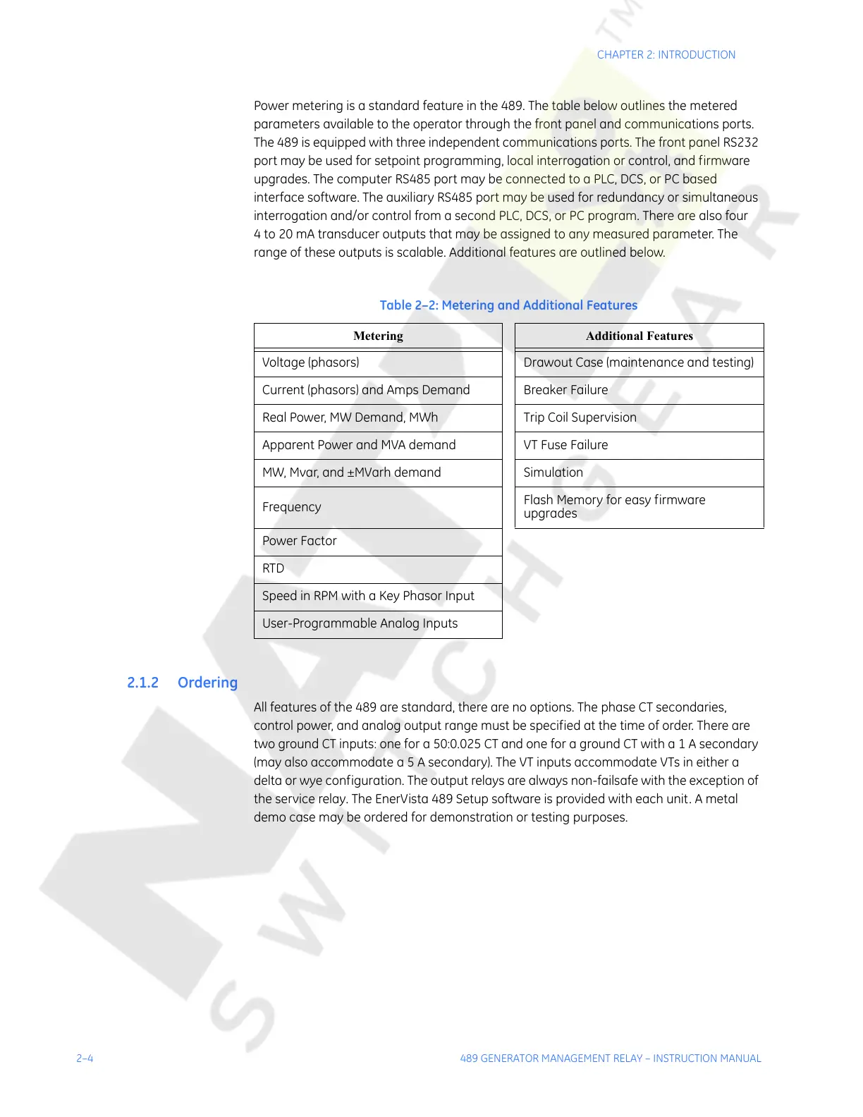
Power metering is a standard feature in the 489. The table below outlines the metered
parameters available to the operator through the front panel and communications ports.
The 489 is equipped with three independent communications ports. The front panel RS232
port may be used for setpoint programming, local interrogation or control, and firmware
upgrades. The computer RS485 port may be connected to a PLC, DCS, or PC based
interface software. The auxiliary RS485 port may be used for redundancy or simultaneous
interrogation and/or control from a second PLC, DCS, or PC program. There are also four
4 to 20 mA transducer outputs that may be assigned to any measured parameter. The
range of these outputs is scalable. Additional features are outlined below.
2.1.2 Ordering
All features of the 489 are standard, there are no options. The phase CT secondaries,
control power, and analog output range must be specified at the time of order. There are
two ground CT inputs: one for a 50:0.025 CT and one for a ground CT with a 1 A secondary
(may also accommodate a 5 A secondary). The VT inputs accommodate VTs in either a
delta or wye configuration. The output relays are always non-failsafe with the exception of
the service relay. The EnerVista 489 Setup software is provided with each unit. A metal
demo case may be ordered for demonstration or testing purposes.
Table 2–2: Metering and Additional Features
Metering Additional Features
Voltage (phasors) Drawout Case (maintenance and testing)
Current (phasors) and Amps Demand Breaker Failure
Real Power, MW Demand, MWh Trip Coil Supervision
Apparent Power and MVA demand VT Fuse Failure
MW, Mvar, and ±MVarh demand Simulation
Frequency
Flash Memory for easy firmware
upgrades
Power Factor
RTD
Speed in RPM with a Key Phasor Input
User-Programmable Analog Inputs
Courtesy of NationalSwitchgear.com