CHAPTER 2: INTRODUCTION
489 GENERATOR MANAGEMENT RELAY – INSTRUCTION MANUAL 2–3
Note
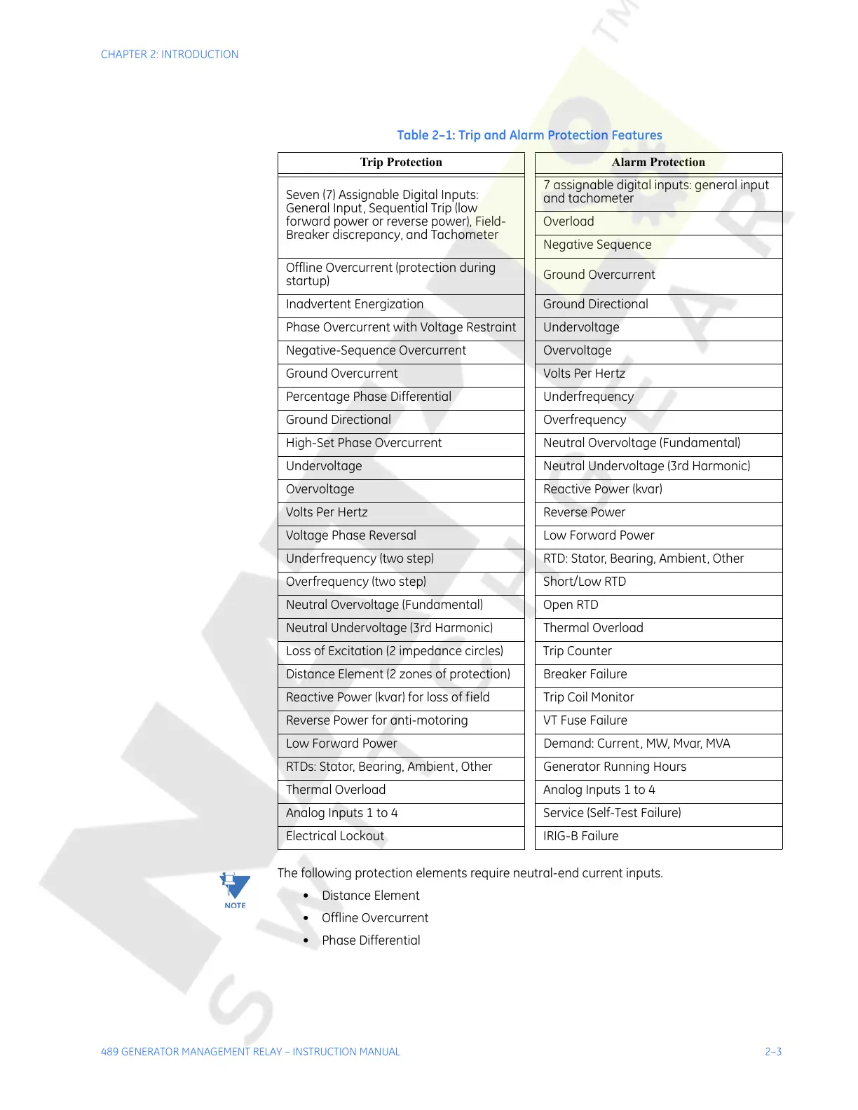
The following protection elements require neutral-end current inputs.
• Distance Element
• Offline Overcurrent
• Phase Differential
Table 2–1: Trip and Alarm Protection Features
Trip Protection Alarm Protection
Seven (7) Assignable Digital Inputs:
General Input, Sequential Trip (low
forward power or reverse power), Field-
Breaker discrepancy, and Tachometer
7 assignable digital inputs: general input
and tachometer
Overload
Negative Sequence
Offline Overcurrent (protection during
startup)
Ground Overcurrent
Inadvertent Energization Ground Directional
Phase Overcurrent with Voltage Restraint Undervoltage
Negative-Sequence Overcurrent Overvoltage
Ground Overcurrent Volts Per Hertz
Percentage Phase Differential Underfrequency
Ground Directional Overfrequency
High-Set Phase Overcurrent Neutral Overvoltage (Fundamental)
Undervoltage Neutral Undervoltage (3rd Harmonic)
Overvoltage Reactive Power (kvar)
Volts Per Hertz Reverse Power
Voltage Phase Reversal Low Forward Power
Underfrequency (two step) RTD: Stator, Bearing, Ambient, Other
Overfrequency (two step) Short/Low RTD
Neutral Overvoltage (Fundamental) Open RTD
Neutral Undervoltage (3rd Harmonic) Thermal Overload
Loss of Excitation (2 impedance circles) Trip Counter
Distance Element (2 zones of protection) Breaker Failure
Reactive Power (kvar) for loss of field Trip Coil Monitor
Reverse Power for anti-motoring VT Fuse Failure
Low Forward Power Demand: Current, MW, Mvar, MVA
RTDs: Stator, Bearing, Ambient, Other Generator Running Hours
Thermal Overload Analog Inputs 1 to 4
Analog Inputs 1 to 4 Service (Self-Test Failure)
Electrical Lockout IRIG-B Failure
Courtesy of NationalSwitchgear.com