CHAPTER 5: SETPOINTS
489 GENERATOR MANAGEMENT RELAY – INSTRUCTION MANUAL 5–97
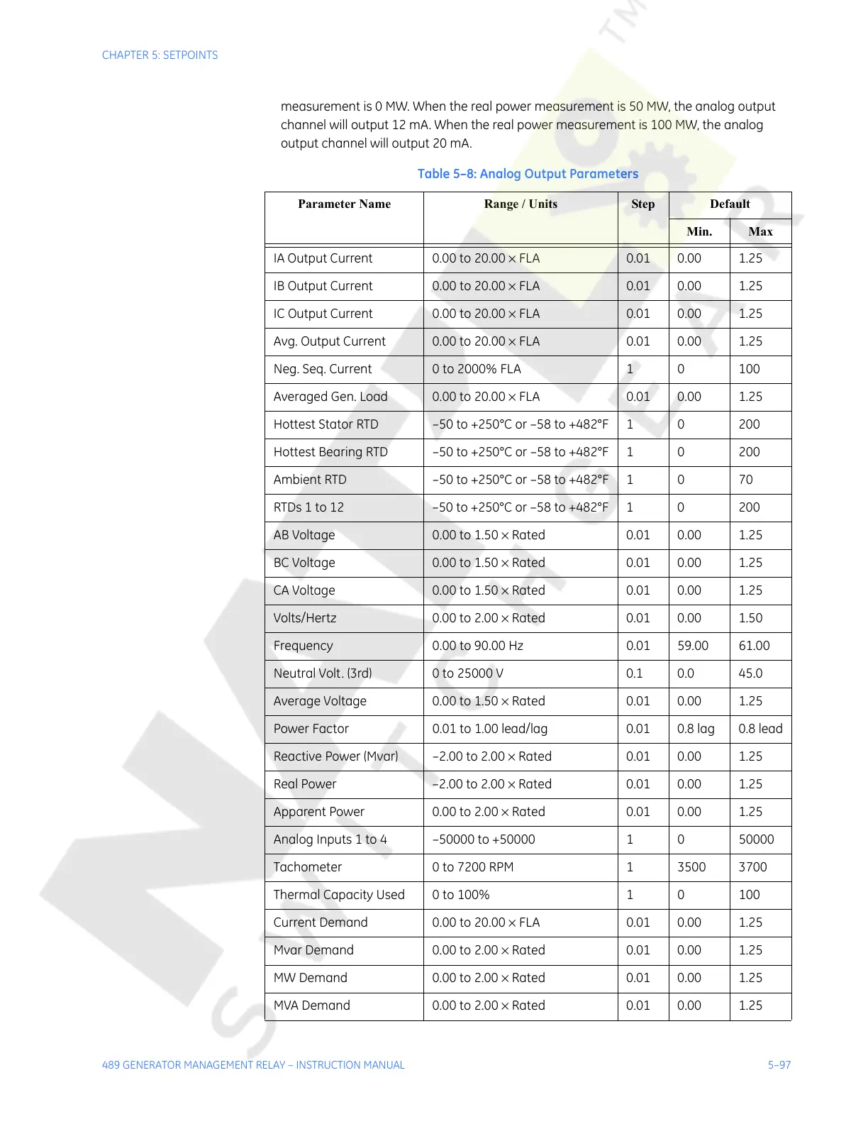
measurement is 0 MW. When the real power measurement is 50 MW, the analog output
channel will output 12 mA. When the real power measurement is 100 MW, the analog
output channel will output 20 mA.
Table 5–8: Analog Output Parameters
Parameter Name Range / Units Step Default
Min. Max
IA Output Current 0.00 to 20.00 × FLA 0.01 0.00 1.25
IB Output Current 0.00 to 20.00 × FLA 0.01 0.00 1.25
IC Output Current 0.00 to 20.00 × FLA 0.01 0.00 1.25
Avg. Output Current 0.00 to 20.00 × FLA 0.01 0.00 1.25
Neg. Seq. Current 0 to 2000% FLA 1 0 100
Averaged Gen. Load 0.00 to 20.00 × FLA 0.01 0.00 1.25
Hottest Stator RTD –50 to +250°C or –58 to +482°F 1 0 200
Hottest Bearing RTD –50 to +250°C or –58 to +482°F 1 0 200
Ambient RTD –50 to +250°C or –58 to +482°F 1 0 70
RTDs 1 to 12 –50 to +250°C or –58 to +482°F 1 0 200
AB Voltage 0.00 to 1.50 × Rated 0.01 0.00 1.25
BC Voltage 0.00 to 1.50 × Rated 0.01 0.00 1.25
CA Voltage 0.00 to 1.50 × Rated 0.01 0.00 1.25
Volts/Hertz 0.00 to 2.00 × Rated 0.01 0.00 1.50
Frequency 0.00 to 90.00 Hz 0.01 59.00 61.00
Neutral Volt. (3rd) 0 to 25000 V 0.1 0.0 45.0
Average Voltage 0.00 to 1.50 × Rated 0.01 0.00 1.25
Power Factor 0.01 to 1.00 lead/lag 0.01 0.8 lag 0.8 lead
Reactive Power (Mvar) –2.00 to 2.00 × Rated 0.01 0.00 1.25
Real Power –2.00 to 2.00 × Rated 0.01 0.00 1.25
Apparent Power 0.00 to 2.00 × Rated 0.01 0.00 1.25
Analog Inputs 1 to 4 –50000 to +50000 1 0 50000
Tachometer 0 to 7200 RPM 1 3500 3700
Thermal Capacity Used 0 to 100% 1 0 100
Current Demand 0.00 to 20.00 × FLA 0.01 0.00 1.25
Mvar Demand 0.00 to 2.00 × Rated 0.01 0.00 1.25
MW Demand 0.00 to 2.00 × Rated 0.01 0.00 1.25
MVA Demand 0.00 to 2.00 × Rated 0.01 0.00 1.25
Courtesy of NationalSwitchgear.com