7–20 489 GENERATOR MANAGEMENT RELAY – INSTRUCTION MANUAL
CHAPTER 7: TESTING
7.3.10 Voltage Restrained Overcurrent Accuracy
Setup the relay as shown in FIGURE 7–3: Secondary Injection Test Setup #3 on page 7–19.
Z In the
S2 SYSTEM SETUP ZV GEN. PARAMETERS menu, set:
GENERATOR RATED MVA: “100 MVA”
GENERATOR VOLTAGE PHASE-PHASE: “12000”
Z In the S2 SYSTEM SETUP ZV VOLTAGE SENSING menu, set:
VT CONNECTION TYPE: “Open Delta”
VOLTAGE TRANSFORMER RATIO: “100:1”
Z In the S5 CURRENT ELEMENTS Z OVERCURRENT ALARM menu, set:
OVERCURRENT ALARM: “Unlatched”
O/C ALARM LEVEL: “1.10 x FLA”
OVERCURRENT ALARM DELAY: “2 s”
O/C ALARM EVENTS: “On”
Z In the S5 CURRENT ELEMENTS ZV PHASE OVERCURRENT menu, set:
PHASE OVERCURRENT TRIP: “Latched”
ENABLE VOLTAGE RESTRAINT: “Yes”
PHASE O/C PICKUP: “1.5 x CT”
CURVE SHAPE: “ANSI Extremely Inv.”
O/C CURVE MULTIPLIER: “2.00”
O/C CURVE RESET: “Instantaneous”
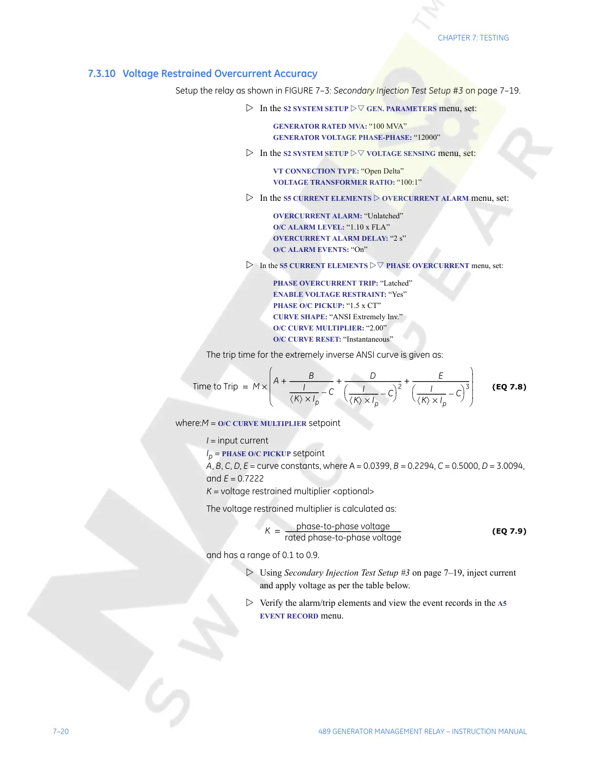
The trip time for the extremely inverse ANSI curve is given as:
(EQ 7.8)
where:M = O/C CURVE MULTIPLIER setpoint
I = input current
I
p
= PHASE O/C PICKUP setpoint
A, B, C, D, E = curve constants, where A = 0.0399, B = 0.2294, C = 0.5000, D = 3.0094,
and E = 0.7222
K = voltage restrained multiplier <optional>
The voltage restrained multiplier is calculated as:
(EQ 7.9)
and has a range of 0.1 to 0.9.
Z Using Secondary Injection Test Setup #3 on page 7–19, inject current
and apply voltage as per the table below.
Z Verify the alarm/trip elements and view the event records in the
A5
EVENT RECORD
menu.
Time to Trip M
A
B
I
K〈〉 I
p
×
------------------- C–
-----------------------------
D
I
K〈〉 I
p
×
------------------- C–
⎝⎠
⎛⎞
2
-------------------------------------
E
I
K〈〉 I
p
×
------------------- C–
⎝⎠
⎛⎞
3
-------------------------------------++ +
⎝⎠
⎜⎟
⎜⎟
⎜⎟
⎛⎞
×=
K
phase-to-phase voltage
rated phase-to-phase voltage
---------------------------------------------------------------------------=
Courtesy of NationalSwitchgear.com