CHAPTER 5: SETPOINTS
489 GENERATOR MANAGEMENT RELAY – INSTRUCTION MANUAL 5–35
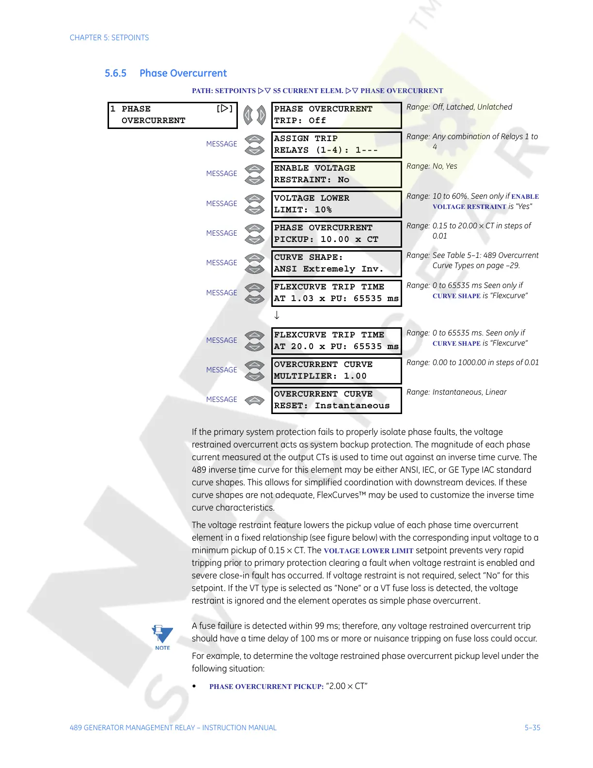
5.6.5 Phase Overcurrent
PATH: SETPOINTS ZV S5 CURRENT ELEM. ZV PHASE OVERCURRENT
If the primary system protection fails to properly isolate phase faults, the voltage
restrained overcurrent acts as system backup protection. The magnitude of each phase
current measured at the output CTs is used to time out against an inverse time curve. The
489 inverse time curve for this element may be either ANSI, IEC, or GE Type IAC standard
curve shapes. This allows for simplified coordination with downstream devices. If these
curve shapes are not adequate, FlexCurves™ may be used to customize the inverse time
curve characteristics.
The voltage restraint feature lowers the pickup value of each phase time overcurrent
element in a fixed relationship (see figure below) with the corresponding input voltage to a
minimum pickup of 0.15 × CT. The
VOLTAGE LOWER LIMIT setpoint prevents very rapid
tripping prior to primary protection clearing a fault when voltage restraint is enabled and
severe close-in fault has occurred. If voltage restraint is not required, select “No” for this
setpoint. If the VT type is selected as “None” or a VT fuse loss is detected, the voltage
restraint is ignored and the element operates as simple phase overcurrent.
Note
A fuse failure is detected within 99 ms; therefore, any voltage restrained overcurrent trip
should have a time delay of 100 ms or more or nuisance tripping on fuse loss could occur.
For example, to determine the voltage restrained phase overcurrent pickup level under the
following situation:
•
PHASE OVERCURRENT PICKUP: “2.00 × CT”
1 PHASE [Z]
OVERCURRENT
PHASE OVERCURRENT
TRIP: Off
Range: Off, Latched, Unlatched
MESSAGE
ASSIGN TRIP
RELAYS (1-4): 1---
Range: Any combination of Relays 1 to
4
MESSAGE
ENABLE VOLTAGE
RESTRAINT: No
Range: No, Yes
MESSAGE
VOLTAGE LOWER
LIMIT: 10%
Range: 10 to 60%. Seen only if ENABLE
VOLTAGE RESTRAINT
is "Yes"
MESSAGE
PHASE OVERCURRENT
PICKUP: 10.00 x CT
Range: 0.15 to 20.00 × CT in steps of
0.01
MESSAGE
CURVE SHAPE:
ANSI Extremely Inv.
Range: See Table 5–1: 489 Overcurrent
Curve Types on page –29.
MESSAGE
FLEXCURVE TRIP TIME
AT 1.03 x PU: 65535 ms
Range: 0 to 65535 ms Seen only if
CURVE SHAPE is “Flexcurve”
↓
MESSAGE
FLEXCURVE TRIP TIME
AT 20.0 x PU: 65535 ms
Range: 0 to 65535 ms. Seen only if
CURVE SHAPE is “Flexcurve”
MESSAGE
OVERCURRENT CURVE
MULTIPLIER: 1.00
Range: 0.00 to 1000.00 in steps of 0.01
MESSAGE
OVERCURRENT CURVE
RESET: Instantaneous
Range: Instantaneous, Linear
Courtesy of NationalSwitchgear.com