CHAPTER 5: SETPOINTS
489 GENERATOR MANAGEMENT RELAY – INSTRUCTION MANUAL 5–45
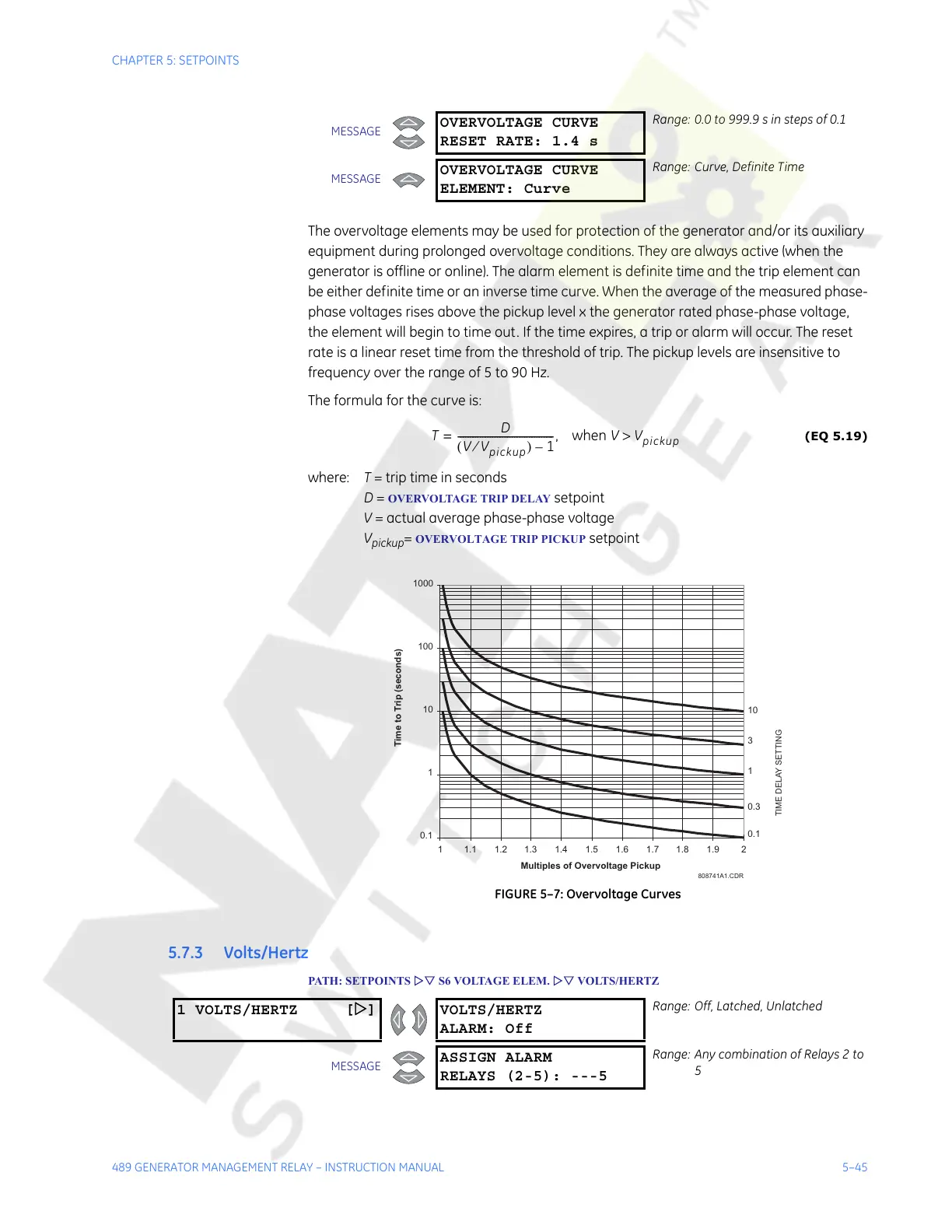
The overvoltage elements may be used for protection of the generator and/or its auxiliary
equipment during prolonged overvoltage conditions. They are always active (when the
generator is offline or online). The alarm element is definite time and the trip element can
be either definite time or an inverse time curve. When the average of the measured phase-
phase voltages rises above the pickup level x the generator rated phase-phase voltage,
the element will begin to time out. If the time expires, a trip or alarm will occur. The reset
rate is a linear reset time from the threshold of trip. The pickup levels are insensitive to
frequency over the range of 5 to 90 Hz.
The formula for the curve is:
(EQ 5.19)
where: T = trip time in seconds
D =
OVERVOLTAGE TRIP DELAY setpoint
V = actual average phase-phase voltage
V
pickup
= OVERVOLTAGE TRIP PICKUP setpoint
FIGURE 5–7: Overvoltage Curves
5.7.3 Volts/Hertz
PATH: SETPOINTS ZV S6 VOLTAGE ELEM. ZV VOLTS/HERTZ
MESSAGE
OVERVOLTAGE CURVE
RESET RATE: 1.4 s
Range: 0.0 to 999.9 s in steps of 0.1
MESSAGE
OVERVOLTAGE CURVE
ELEMENT: Curve
Range: Curve, Definite Time
T
D
VV
pickup
⁄()1–
---------------------------------------= , when VV
pickup
>
808741A1.CDR
0.1
1
10
100
1000
1 1.1 1.2 1.3 1.4 1.5 1.6 1.7 1.8 1.9 2
Multiples of Overvoltage Pickup
10
3
1
0.3
0.1
Time to Trip (seconds)
TIME DELAY SETTING
1 VOLTS/HERTZ [Z] VOLTS/HERTZ
ALARM: Off
Range: Off, Latched, Unlatched
MESSAGE
ASSIGN ALARM
RELAYS (2-5): ---5
Range: Any combination of Relays 2 to
5
Courtesy of NationalSwitchgear.com