5–56 489 GENERATOR MANAGEMENT RELAY – INSTRUCTION MANUAL
CHAPTER 5: SETPOINTS
All relay quantities are in terms of secondary impedances. The formula to convert primary
impedance quantities to secondary impedance quantities is provided below.
(EQ 5.27)
where: Z
primary
= primary ohms impedance;
CT Ratio = programmed CT ratio,
if CT ratio is 1200:5 use a value of 1200 / 5 = 240;
VT Ratio = programmed VT ratio, if VT ratio is 100:1 use a value of 100
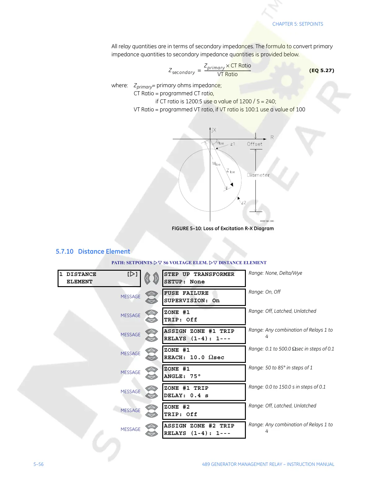
FIGURE 5–10: Loss of Excitation R-X Diagram
5.7.10 Distance Element
PATH: SETPOINTS ZV S6 VOLTAGE ELEM. ZV DISTANCE ELEMENT
Z
ondarysec
Z
primary
CT Ratio×
VT Ratio
------------------------------------------------=
1 DISTANCE [Z]
ELEMENT
STEP UP TRANSFORMER
SETUP: None
Range: None, Delta/Wye
MESSAGE
FUSE FAILURE
SUPERVISION: On
Range: On, Off
MESSAGE
ZONE #1
TRIP: Off
Range: Off, Latched, Unlatched
MESSAGE
ASSIGN ZONE #1 TRIP
RELAYS (1-4): 1---
Range: Any combination of Relays 1 to
4
MESSAGE
ZONE #1
REACH: 10.0 Ωsec
Range: 0.1 to 500.0 Ωsec in steps of 0.1
MESSAGE
ZONE #1
ANGLE: 75°
Range: 50 to 85° in steps of 1
MESSAGE
ZONE #1 TRIP
DELAY: 0.4 s
Range: 0.0 to 150.0 s in steps of 0.1
MESSAGE
ZONE #2
TRIP: Off
Range: Off, Latched, Unlatched
MESSAGE
ASSIGN ZONE #2 TRIP
RELAYS (1-4): 1---
Range: Any combination of Relays 1 to
4
Courtesy of NationalSwitchgear.com