2–6 489 GENERATOR MANAGEMENT RELAY – INSTRUCTION MANUAL
CHAPTER 2: INTRODUCTION
2.2 Specifications
2.2.1 Inputs
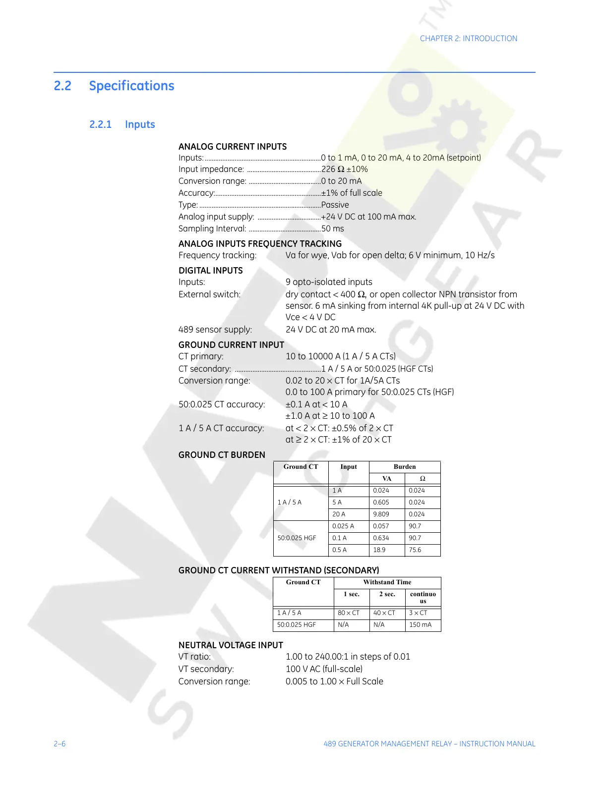
ANALOG CURRENT INPUTS
Inputs:..................................................................0 to 1 mA, 0 to 20 mA, 4 to 20mA (setpoint)
Input impedance: ..........................................226 Ω ±10%
Conversion range: .........................................0 to 20 mA
Accuracy:............................................................±1% of full scale
Type: .....................................................................Passive
Analog input supply: ....................................+24 V DC at 100 mA max.
Sampling Interval: .........................................50 ms
ANALOG INPUTS FREQUENCY TRACKING
Frequency tracking: Va for wye, Vab for open delta; 6 V minimum, 10 Hz/s
DIGITAL INPUTS
Inputs: 9 opto-isolated inputs
External switch: dry contact < 400 Ω, or open collector NPN transistor from
sensor. 6 mA sinking from internal 4K pull-up at 24 V DC with
Vce < 4 V DC
489 sensor supply: 24 V DC at 20 mA max.
GROUND CURRENT INPUT
CT primary: 10 to 10000 A (1 A / 5 A CTs)
CT secondary: .................................................1 A / 5 A or 50:0.025 (HGF CTs)
Conversion range: 0.02 to 20 × CT for 1A/5A CTs
0.0 to 100 A primary for 50:0.025 CTs (HGF)
50:0.025 CT accuracy: ±0.1 A at < 10 A
±1.0 A at ≥ 10 to 100 A
1 A / 5 A CT accuracy: at < 2 × CT: ±0.5% of 2 × CT
at
≥ 2 × CT: ±1% of 20 × CT
GROUND CT BURDEN
GROUND CT CURRENT WITHSTAND (SECONDARY)
NEUTRAL VOLTAGE INPUT
VT ratio: 1.00 to 240.00:1 in steps of 0.01
VT secondary: 100 V AC (full-scale)
Conversion range: 0.005 to 1.00 × Full Scale
Ground CT Input Burden
VA Ω
1A / 5A
1 A 0.024 0.024
5 A 0.605 0.024
20 A 9.809 0.024
50:0.025 HGF
0.025 A 0.057 90.7
0.1 A 0.634 90.7
0.5 A 18.9 75.6
Ground CT Withstand Time
1 sec. 2 sec. continuo
us
1A / 5A 80× CT 40 × CT 3 × CT
50:0.025 HGF N/A N/A 150 mA
Courtesy of NationalSwitchgear.com