Do you have a question about the GE Multilin 750 and is the answer not in the manual?
Basic overview of the guide's purpose and content.
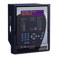
Describes the relay's function and capabilities.
Lists protection/control functions with ANSI codes.
Lists monitoring/control functions.
Describes the physical casing of the relay.
Details how to mount the relay unit in a panel.
Explains how to remove and insert the relay unit.
Describes Ethernet connection for the relay.
Discusses voltage and ground connection requirements.
Explains how to connect logic inputs to the relay.
Describes analog input/output connections.
Details initial system configuration setpoints.
Configuration of logic input parameters.
Configuration of protection element settings.
Introduces the setup software.
Discusses communication hardware for the software.
Steps to set up serial communication.
Describes the quick connection method.
Steps for Ethernet setup.
Finalizing relay connection via software.
Establishing communication with the relay.
How to input settings into the relay.
Managing setpoint files.
Procedure to save settings to a file.
Incorporating existing files into the software.
Procedure to create new configuration files.
Updating setpoint files for firmware compatibility.
How to print configuration and real-time data.
Restoring settings after firmware upgrade.
Essential step before firmware upgrade.
Procedure for installing new firmware.
Viewing data from specific events.
Captures and logs system events.
Displays waveform traces and digital states.
Capturing and analyzing transient events.
Samples and records system values.
Viewing and analyzing recorded events.
Programming the relay's Modbus addresses.
Monitoring real-time relay data.
Overview of a typical relay application.
Specifies power system characteristics for the example.
Defines control system needs for the example.
Details CT and VT specifications for the example.
Configuration for phase overcurrent protection.
Configuration for neutral overcurrent protection.
Setting system characteristics.
Configuration of logic input parameters.
Configuration of protection elements.
Introduces additional settings beyond basic setup.
Configuring undervoltage protection settings.
Configuration of auxiliary relay outputs.
Managing different sets of protection parameters.
Contact information for product support.
| Type | Feeder Protection Relay |
|---|---|
| Frequency | 50/60 Hz |
| Mounting Type | Panel Mount |
| Enclosure | IP54 |
| Communication Protocols | DNP3, Modbus, IEC 61850 |
| Protection Functions | Overcurrent |
| Display | LCD |
| Current Rating | Up to 5A continuous |


 Loading...