Electrical installation
6 750/760 Quick Reference Guide
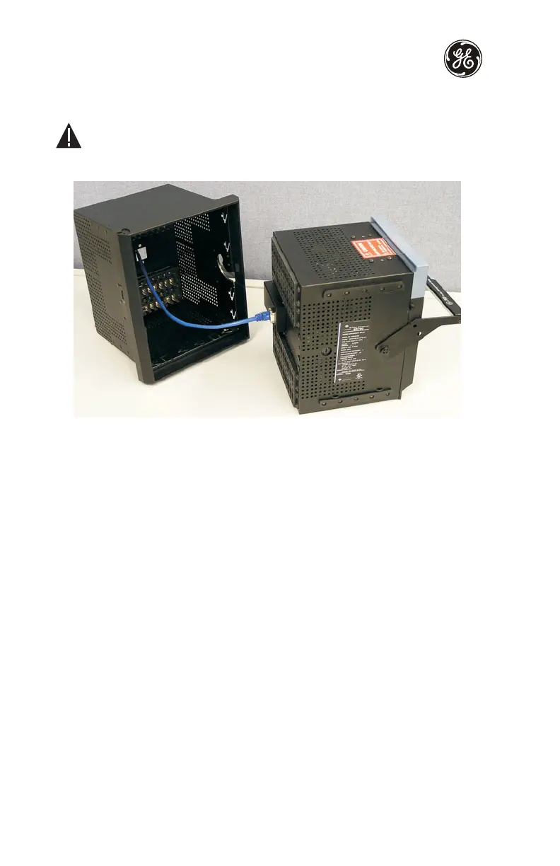
The unit may then be re-inserted by first connecting the network cable to the units' rear
RJ45 connector (see step 3 of Unit withdrawal and insertion on page 4).
Ensure that the network cable does not get caught inside the case while sliding
in the unit. This may interfere with proper insertion to the case terminal blocks
and damage the cable.
Figure 7: Ethernet Cable Connection
ELECTRICAL INSTALLATION
Ratings and polarities
Ensure that the control voltage matches the ratings and polarities of the relay power
supply. Control power supplied to the relay must match the installed power supply range.
All grounds MUST be connected for normal operation regardless of control power supply
type. The label found on the left side of the relay specifies its order code or model number.
The installed power supply's operating range will be one of the following.
• LO: 20 to 60 V DC or 20 to 48 V AC
• HI: 88 to 300 V DC or 70 to 265 V AC
The relay ground connections should be connected directly to the ground bus, using the
shortest practical path. A tinned copper, braided, shielding and bonding cable should be
used. As a minimum, 96 strands of number 34 AWG should be used. Belden catalog number
8660 is suitable.
The current transformer input ratings and polarities match the secondary ratings of the
corresponding CT. For the correct operation of many relay features, the instrument
transformer polarities shown below in the Typical Wiring Diagram should be followed.
IMPORTANT: The phase and ground current inputs will correctly measure to 20 times
the current input's nominal rating.
CAUTION

 Loading...


