Application example
750/760 Quick Reference Guide 45
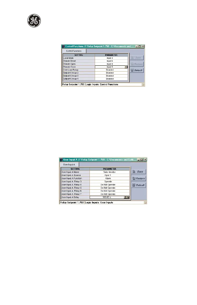
3. Inputs 3, 4, 5, and 6 will perform control functions. Select the Setpoints > S3 Logic
Inputs > Control Functions menu item to display the following window:
4. Change the corresponding setpoints, and then press Save.
To setup an Alarm-after-Delay input, make the following changes to the S3 LOGIC INPUTS
ZV USER INPUT A setpoints page. Press the message down key after each setpoint is
completed to move to the next message.
USER INPUT A NAME: “Substation Monitor”
USER INPUT A SOURCE: “Input 1”
USER INPUT A FUNCTION: “Alarm”
USER INPUT A RELAYS (3-7): “3----”
USER INPUT A DELAY: “100.00 s”
Using EnerVista 750/760 Setup, define their functionality as follows.
1. Select the Setpoints > S3 Logic Inputs > User Inputs > User Input A menu item to
display the following window:
2. Change the corresponding setpoints as indicated, and then press Save.
S5 Protection setpoints
The S5 Protection setpoints page contains setpoints for entering protection element
characteristics. In our example, these characteristics are specified under the S5
PROTECTION
Z PHASE CURRENT and S5 PROTECTION ZV NEUTRAL CURRENT headings.
From this data and the resulting calculations, program the page S5 setpoints as indicated.
When setting the relay for the first time, other setpoints not listed in this example will be left
disabled.
For the Phase Time Overcurrent 1 element, enter the following values in the S5
PROTECTION
Z PHASE CURRENT Z PHASE TIME OVERCURRENT 1 page. Press the
message down key after each setpoint is completed to move to the next message.

 Loading...


