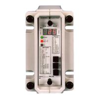
Do you have a question about the GE MFAC 14 and is the answer not in the manual?
Steps to prevent damage from static electricity when handling electronic modules.
Guidelines for using wrist straps and maintaining earthing for measurements.
Recommendation for dedicated areas for detailed investigations and modifications.
Information for safe installation and handling of products.
Meaning of symbols used on equipment and documentation for safety.
Safety warnings for CT circuits, resistors, batteries, and module handling.
Safety advice for viewing fibre optic devices.
Precautions for charged capacitors during insulation testing.
Safety for electrical/mechanical adjustments, module handling, and test plugs.
Safely discharging capacitors and general product disposal guidance.
Recommended maximum rating for the external protective fuse.
Classification of insulation requirements for user safety.
Qualification standards for insulation category and test levels.
Compliance demonstrated by reference to generic safety standards.
Compliance with Low Voltage Directive and safety standards.
Care and site selection for protective relays to prevent failure.
Handling relays during unpacking to avoid damage and setting alteration.
Recommendations for storing relays to prevent dust and moisture damage.
Requirements for an installation site to be clean, dry, and well-illuminated.
Overview of MFAC 14/MFAC 34 relay and calculation of settings.
Definitions of abbreviations used in relay settings and calculations.
Formula and method for calculating the minimum setting voltage for stability.
Initial checks before commissioning, including inspection and armature actuation.
Requirement for the minimum knee point voltage of the current transformer.
Table detailing relay operating current with metrosil for different voltage settings.
Formula for calculating primary current for operation and adjustments.
Function of external metrosils in protecting CT and relay circuits.
Detailed checks for relay damage, serial numbers, and armature movement.
Checking armature movement and contact follow-through for proper operation.
Verifying external wiring against the relay diagram and rating information.
Importance of internal CT shorting switches when the module is withdrawn.
Guidance on connecting test blocks (MMLG) and specific terminals.
Ensuring the case earthing connection is made to a local earth bar.
Procedures for insulation testing of circuits and earth.
Standard terminal allocation for single and triple pole relays.
Instruction to check the relay only at the calculated setting.
List of necessary test equipment for secondary injection testing.
General advice for secondary injection testing using MMLG test blocks.
Electrical check of CT shorting switches with the relay removed.
Procedure for testing relay operating current and voltage.
Verification of the drop-off to pick-up ratio.
Essential testing to prove correct polarity of current transformers.
Checking primary fault setting by injecting current into CTs.
Checking current transformer connections and stability during through faults.
Recommendation for periodic inspection and testing every 12 months.
Repeating secondary injection tests to prove operation and check contacts.
Methods for measuring armature gap and contact pressures.
Specifications for clearance between armature and back stop.
Specification for the nominal armature gap when open.
Force requirements for closing and lifting make contacts.
Settings for self-reset units, checking flag fall clearance.
Troubleshooting steps for relay failure to operate, including connections and input current.
Troubleshooting for output contacts not changing state, checking terminals and contacts.
How to quote model and component numbers when ordering spares.
Procedure for returning equipment for repair, including RMA form and test results.
Fields to fill in for station, relay model, settings, and circuit details.
Table for recording secondary voltage test results for each phase.
Checkbox for recording the drop off/pick up ratio test result.
Table for recording primary current and voltage test results for each phase.
Tables for recording stability check results for restricted earth fault and circulating current.
Fields for signatures of the commissioning engineer and customer witness.
Fields for Qty, Type of Material, Serial No., Fault description, etc.
Options for firmware updates and relay return case.
Required address details for customs and invoicing.
Conditions for import invoice, purchase order, authorization, and packaging.
Guidelines for cleaning, packaging, and secondary packing of returned devices.
| Number of Functions | 14 |
|---|---|
| Output Contacts | SPDT |
| Mounting | DIN Rail |
| Input Voltage | 24-240VAC/DC |
| Operating Temperature | -20 to 60°C |


