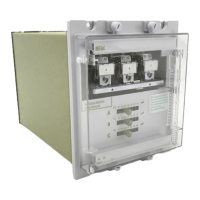
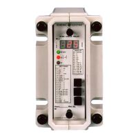
Publication R6001 is a leaflet on the
modular
integrated drawout system of
protective relays.
Publication R6014 is a list of
recommended
suppliers for the pre-
insulated connectors.
Section
2. COMMISSIONING
2.1 Description of relay, calculation of setting and commissioning preliminaries
2.1.1 Description of MFAC 14/MFAC
34
This is a voltage operated relay having seven equally spaced settings of
15–185 volts, 25–175 volts, 25–375 volts or 100–400 volts which may be selected
by means of a plug bridge.
The relays may be used for any type of high impedance circulating
current protection.
2.1.2 List of abbreviations.
I
E
=
Current transformer
exciting current at relay setting voltage (referred to the
CT secondary current)
I
F
=
Maximum value of primary
through
fault current for which protection must
remain stable.
I
FM
=
Maximum value of primary fault current for internal fault.
I
P
=
Primary current for operation of protection.
I
R
=
Relay operating current.
I
SH
= Current
in
shunt
resistor at relay setting
V
R
.
N
= Turns
ratio of current transformer.
n
=
No. of current
transformers
in parallel with
relay.
R
CT
=
Secondary resistance of current transformer.
R
L
=
Lead resistance between
furthest
current
transformer
and relay
connection point.
R
R
=
Relay impedance.
R
SH
=
Value of
shunt
resistor.
V
F
=
The theoretical voltage which would be produced across the relay circuit
under internal fault condition.
V
F
=
I
FM
(R
CT
+
2R
L
+
R
R
)
N
V
K
=
Knee point voltage of current transformer.
V
P
=
Peak voltage across relay circuit under
maximum
internal fault conditions.
V
S
=
Minimum
setting voltage. (calculated)
V
R
=
Relay setting voltage.
2.1.3 Calculation of relay setting.
The
minimum
setting voltage to ensure stability is
V
S
≥
I
F
(R
CT
+
2R
L
)
N
The relay plug setting voltage V
R
must
be set to the nearest tap above
V
S
.
10

 Loading...


