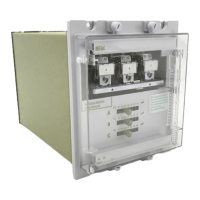
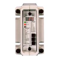
The
minimum
knee point voltage
must
be
V
K
≥
2V
R
The operating current of the relay is 38mA, irrespective of tap selected, excluding
the current drawn by the external metrosil. When a standard
metrosil
is included
with the relay, the relay operating current including the
metrosil
is given in the table
below.
It
must
be appreciated that
metrosils
have large tolerances and these figures
are given for guidance only.
a) Low range relay (5V steps)
Setting voltage
V
R
15
50
75
100
125
150
175
185
(including metrosil, C
=
1100)
The primary current for operation is given
by
I
P
=
N (I
R
+
n
I
E
)
If the
resultant
value of I
P
is too low it may be increased by the addition of a
shunt resistor R
SH
to give a current of
I
SH
=
V
R
R
SH
The new increased value of primary current
I
P
=
N (I
R
+
nI
E
+
I
SH
)
External metrosils.
Each FAC relay is applied with an external
metrosil
which
must
be wired across
the relay circuit. This provides a
shunt
circuit for high internal fault currents and
prevents a high voltage being developed across the CT and relay circuits.
2.1.4 Commissioning preliminaries.
Inspection.
Carefully examine the module and case to see that no damage has occurred
during transit. Check that the relay serial number on the module, case and cover
are identical, and that the model number and rating information are correct.
Carefully remove any elastic bands/packing fitted for transportation purposes.
Carefully actuate the armature of each unit in turn with a small screwdriver/probe.
Note that immediately after the point where any normally open contacts just make
11

 Loading...


