CHAPTER 5: SETPOINTS
489 GENERATOR MANAGEMENT RELAY – INSTRUCTION MANUAL 5–71
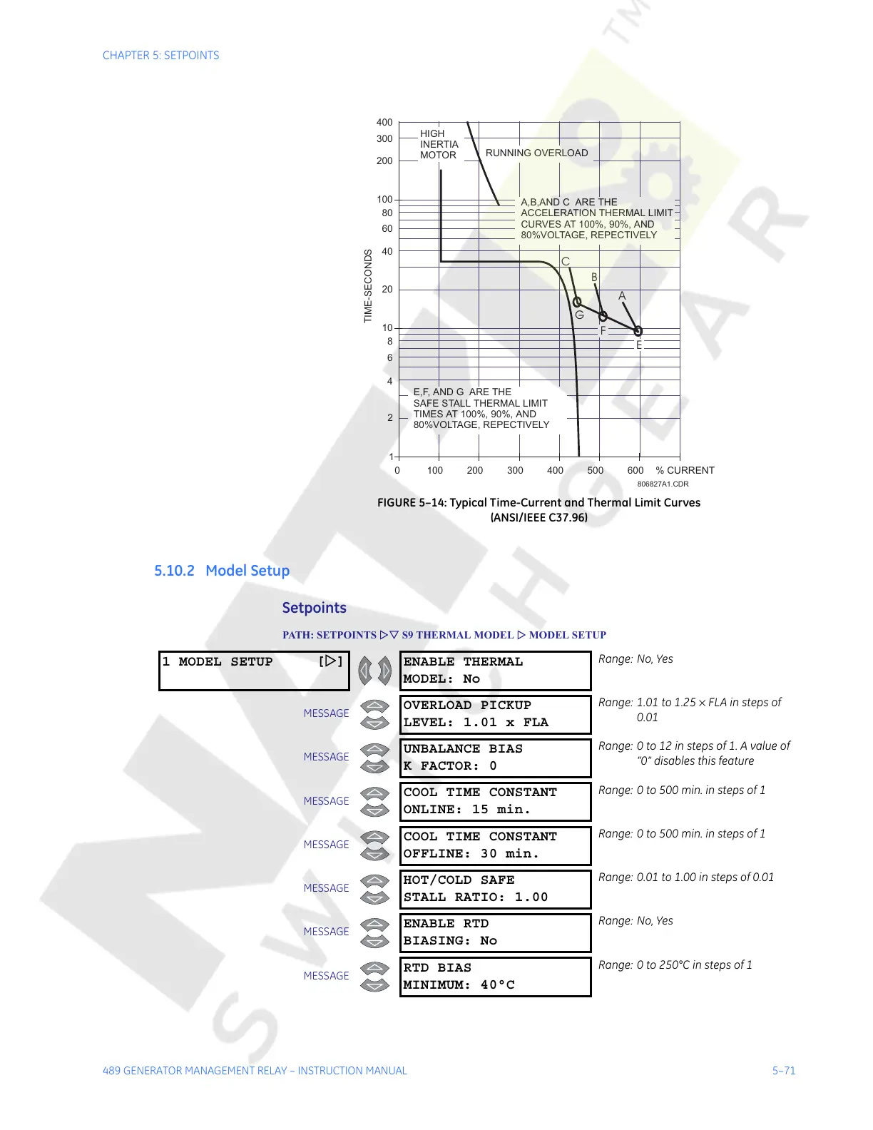
FIGURE 5–14: Typical Time-Current and Thermal Limit Curves
(ANSI/IEEE C37.96)
5.10.2 Model Setup
Setpoints
PATH: SETPOINTS ZV S9 THERMAL MODEL Z MODEL SETUP
1
10
8
6
4
2
100
80
60
40
20
200
300
400
0 100 200 300 400 500 600 % CURRENT
TIME-SECONDS
HIGH
INERTIA
MOTOR
RUNNING OVERLOAD
A
G
B
C
A,B,ANDC ARE THE
ACCELERATION THERMAL LIMIT
CURVES AT 100%, 90%, AND
80%VOLTAGE,REPECTIVELY
E,F, AND GARE THE
SAFE STALL THERMAL LIMIT
TIMES AT 100%, 90%, AND
80%VOLTAGE,REPECTIVELY
E
F
806827A1.CDR
1 MODEL SETUP [Z] ENABLE THERMAL
MODEL: No
Range: No, Yes
MESSAGE
OVERLOAD PICKUP
LEVEL: 1.01 x FLA
Range: 1.01 to 1.25 × FLA in steps of
0.01
MESSAGE
UNBALANCE BIAS
K FACTOR: 0
Range: 0 to 12 in steps of 1. A value of
“0” disables this feature
MESSAGE
COOL TIME CONSTANT
ONLINE: 15 min.
Range: 0 to 500 min. in steps of 1
MESSAGE
COOL TIME CONSTANT
OFFLINE: 30 min.
Range: 0 to 500 min. in steps of 1
MESSAGE
HOT/COLD SAFE
STALL RATIO: 1.00
Range: 0.01 to 1.00 in steps of 0.01
MESSAGE
ENABLE RTD
BIASING: No
Range: No, Yes
MESSAGE
RTD BIAS
MINIMUM: 40°C
Range: 0 to 250°C in steps of 1
Courtesy of NationalSwitchgear.com