S4 Elements745
Transformer Management Relay
Setpoints
http://www.GEindustrial.com/multilin
5–84
GE Multilin
Transformer Overload PATH: SETPOINTS !" S4 ELEMENTS !" XFORMER OVERLOAD
• TRANSFORMER OVERLOAD PICKUP: This setting identifies the level of
transformer overload, where the pickup delay starts timing. The setting is
expressed as a percentage of the transformer base MVA rating, and is normally
set at or above the maximum rated MVA from the transformer nameplate.
• XFMR OVERTEMP ALARM SIGNAL: Select any logic input that, when
asserted, indicates the transformer cooling system has failed and an over-
temperature condition exists. The logic input should be connected to the
transformer winding temperature alarm contacts.
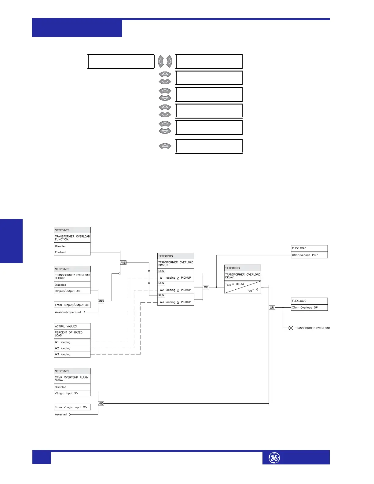
FIGURE 5–44: Transformer Overload Scheme Logic
! XFORMER [!]
OVERLOAD
TRANSFORMER OVERLOAD
FUNCTION: Disabled
Range: Enabled, Disabled
MESSAGE
TRANSFORMER OVERLOAD
TARGET: Self-Reset
Range: Self-Reset, Latched, None
MESSAGE
TRANSFORMER OVERLOAD
PICKUP: 208% rated
Range: 50 to 300% of Rated Load in
steps of 1
MESSAGE
TRANSFORMER OVERLOAD
DELAY: 10 s
Range: 0 to 60000 s in steps of 1
MESSAGE
TRANSFORMER OVERLOAD
BLOCK: Disabled
Range: Logc Inpt 1 to 16, Virt Inpt 1 to
16, Output Rly 2 to 8, SelfTest
Rly, Vir Outpt 1 to 5, Disabled
MESSAGE
XFMR OVERTEMP ALARM
SIGNAL: Disabled
Range: Disabled, Logc Inpt 1 to 16