Step 3:
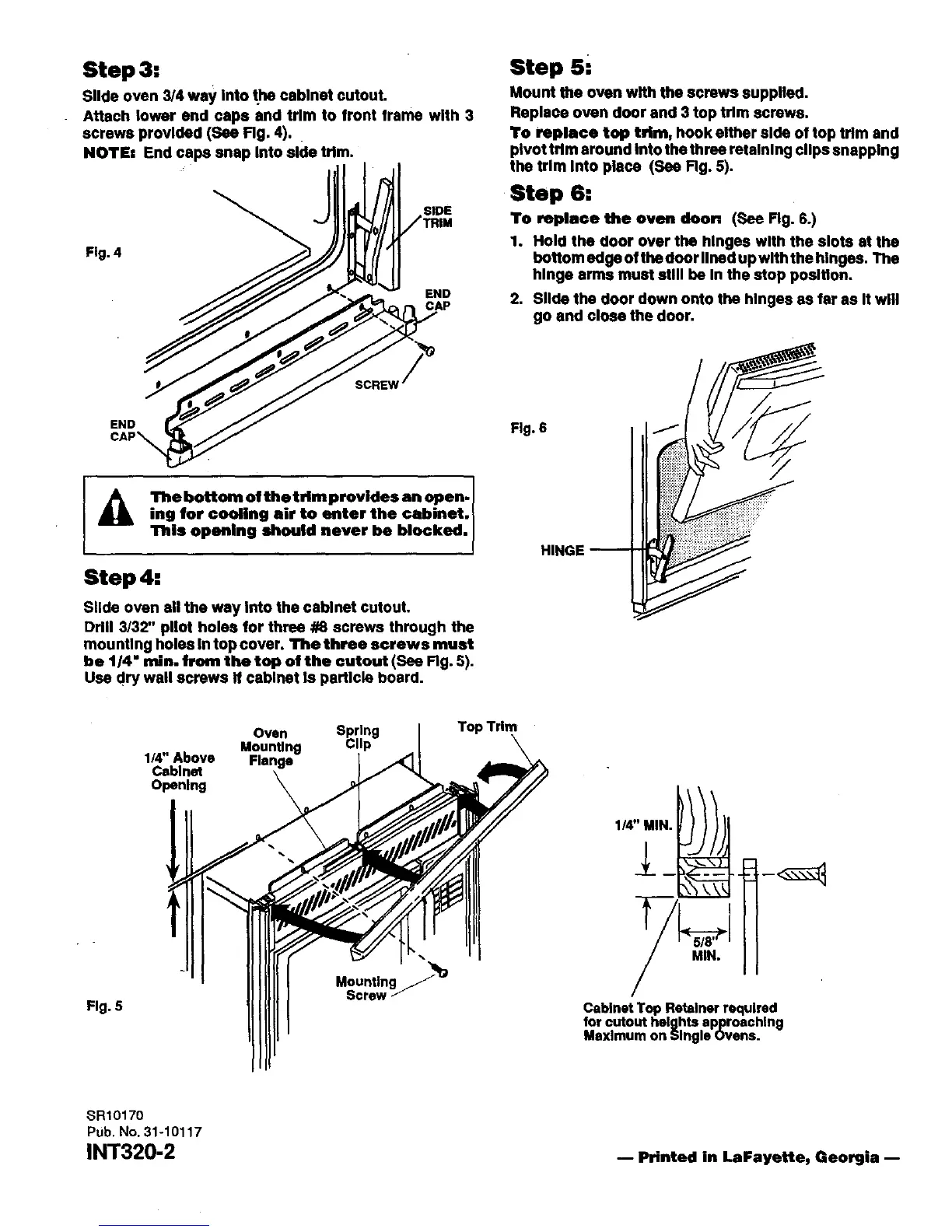
Slide oven 3/4 way Into the cabinet cutout.
Attach lower end caps and trim to front frame with 3
screws provided (See Fig. 4).
NOTEI End caps snap Into side trim.
Fig. 4
SIDE
END
CAP
SCREW/'_
Step 5i
Mount the oven with the screws supplied.
Replace oven door and 3 top trim screws.
To replace top trim, hook either side of top trim and
pivot trim around into the three rstalnlng clips snapping
the trim Into place (See Fig. 5).
Step 6:
TO replace the oven (loon (See Fig. 6.)
1. Hold the door over the hinges with the slots at the
bottom edge of the door lined up with the hlngee. The
hinge arms must still be In the stop position.
2. Slide the door down onto the hinges as far as It will
go and close the door.
END
CAP_
Fig. 6
_&A The bottom of the trim provides an open.
ing for cooling air to enter the cabinet.
I -- This opening should never be blocked. I
Step 4:
Slide oven ell the way into the cabinet cutout.
Drill 3/32" pilot holes for three #8 screws through the
mounting holes In top cover. The three screws must
be 1/4" rain. front the top of the cutout (See Fig. 5).
Use dry wall screws if ceblnst Is particle board.
HINGE --
Fig. 5
Oven
Mounting
1/4" Above Flange
Cabinet
Opening
Spring
Clip
Top Trim
CabinetTop Retainerrequired
for cutout heightsapproaching
Maximumon SingleOvens.
-4
SR1017O
Pub. No. 31-10117
INT320-2 -- Printed in LaFayette, Georgia --




 To Previous Page