7
Installation
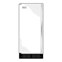
Automatic Icemaker
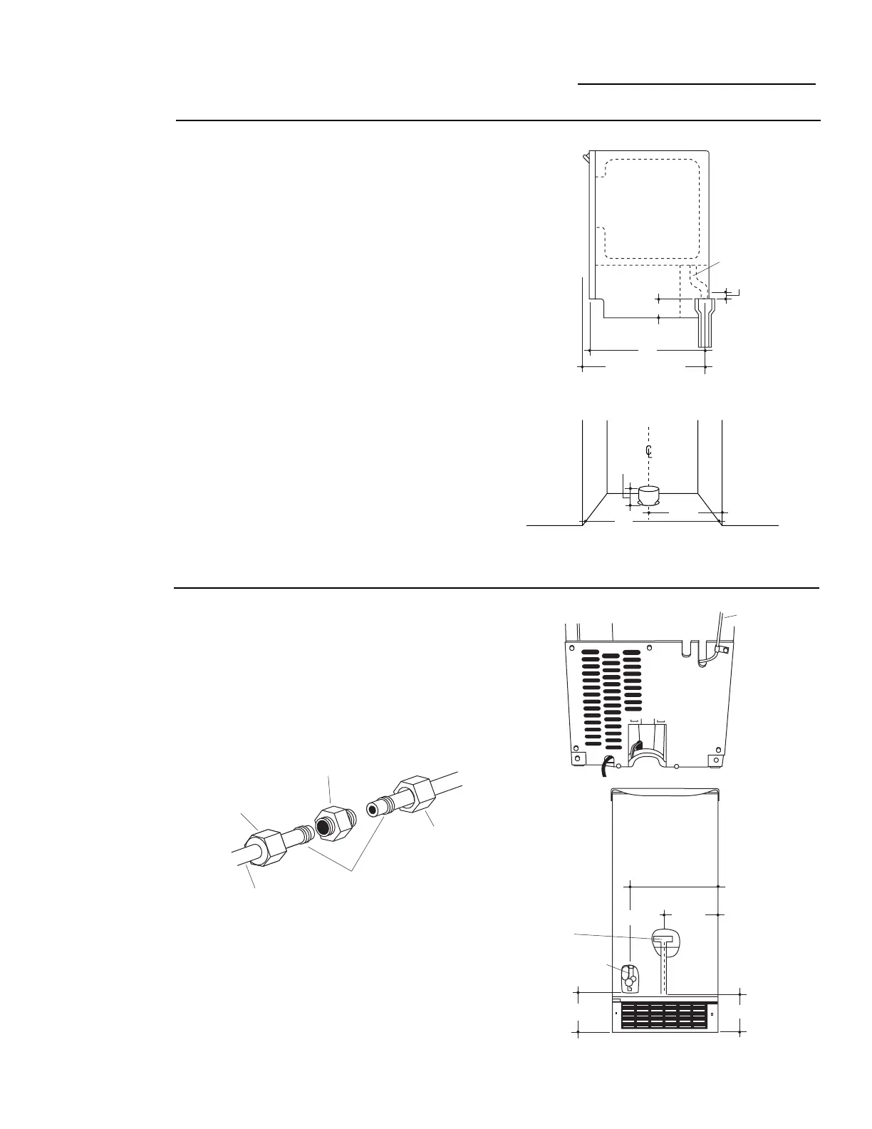
This ice machine is equipped with a gravity
drain to prevent water from flowing back into
the ice machine storage bin and potentially
flowing onto the floor. A floor drain is
acceptable. The ideal installation has a
standpipe with a 2” to 1-1/2” PVC drain
reducer installed directly below the outlet of
the drain tube:
– 7-1/2" to centerline of the opening.
– Approximately 3-1/2" high.
– 22" from the front, or 22-3/4" when
installing a 3/4" door panel.
• Drain lines must be at least 5/8” inside
diameter.
Note:
A drain pump is necessary when a floor drain is not
available. Order ZPK1 Drain Pump Kit or contact your local
plumber for a recommended pump available in your area.
TEST DRAIN HOSE ALIGNMENT: Before sliding the ice
machine into the cabinet opening check to be sure the bottom of
the drain tube is below the rear cover. To test, place a pan below
the drain hose. Pour a gallon of water into the ice bin and check to
be sure that water does not wet the rear cover.
Connect
the Drain
• The water line should be flushed to clear
any foreign material before connecting to
the icemaker.
• Connect the waterline to the water supply
tube outside of the rear access cover.
• Use a standard plumbing female connector
or union for 1/4" copper tubing that can be
purchased locally.
Connect
Water
Supply
1"
22"
Drain Hose
3-1/2"
22-3/4" With 3/4"
Custom Panel
3-1/2"
High
7-1/2"
Locate Standpipe in exact
Center of The Cutout
15"
7-5/16"
12-1/4"
4-5/8"5-11/16"
Water Pan
Drain
Water Valve
Water
Supply
Line
Coupling
(Not Supplied)
Nut
(Supplied)
Ferrule
(Not Supplied)
Line to
Icemaker
Nut
(Supplied)
• Make sure there are no sharp bends or kinks
which could restrict water flow.
• Slide the ice machine into its permanent
location.
• To prevent rattling, be sure the copper
tubing does not touch the side wall or other
parts inside the cabinet.
• Open the shut-off valve. Check for leaks.
Tighten any connections (including connec-
tions at the valve) if necessary.