6
BE1-27, 59, 27/59
CONNECTIONS
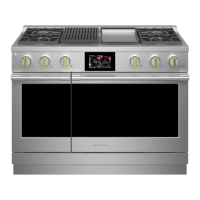
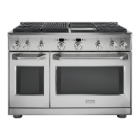
Figure 4 - Control Circuits
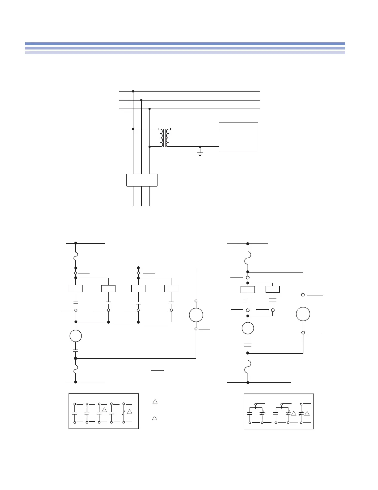
Figure 3 - Voltage Sensing
TARGET
TARGET
POWER
T
I
52a
1
1
2
2
1
2
AUXILIARY CONTACTS
AUXILIARY CONTACTS
27/59
17
TOV
TUV
T
IIUV IOV
27/59
19
27/59
15
27/59
16
27/59
15
27/59
14
27/59
14
27/59
14
27/59
20
27/59
18
27 or 59
8
27 or 59
18
27 or 59
5
27 or 59
4
27 or 59
3
27 or 59
1
27 or 59
10
27 or 59
2
27 or 59
19
27 or 59
19
27 or 59
9
27 or 59
20
27 or 59
20
LEGEND:
When Option 2 is A or B, the NC contacts
associated with K6 (terminals 14 and 15)
are dedicated for the Power Supply
Status Output.
When Option 2 is A or B, the NC contacts
associated with K4 (terminals 19 and 20)
are dedicated for the Power Supply
Status Output.
27/59
52a
52TC
TUV
TOV
IUV
IOV
Under/Overvoltage Relay
Breaker Aux. Contacts
Breaker Trip Coil
Timed Undervoltage
Timed Overvoltage
Instantaneous Undervoltage
Instantaneous Overvoltage
52a
52
TC
52
TC
27/59
1
27/59
2
27/59
10
27/59
13
27/59
11
27/59
12
27/59
4
27/59
3
POWER
TARGET
TARGET
TARGET
TARGET
+ +
-
-
TOV TUV
IOV
IUV
A
B
C
6
7
52
BE1-27
BE1-59
BE1-27/59