2
www.GEindustrial.com/Multilin
SB-1 Control & Transfer Switches
Design Information
SB-1 Switches are rotary, cam-
operated devices for the control
of electrically operated circuit
breakers, small motors, magnetic
switches and similar devices.
Another important use is for the
transfer of current and potential
for meters, instruments, and
relays. Also, there are many
general control applications for
which this switch can be used.
SB-1 Switches are built up in a
series of individual stages, each
nested into the other with a
common fixed contact support,
operating shaft, and front and
rear supports. The stack is held
together with two tie bolts
threaded into the front support.
Each stage consists of an insulat-
ing barrier carrying one or two
moving contacts and three oper-
ating cams. Rotation of the shaft
moves the cams directly against
the contact arms so that positive
high pressure results at the
contact. Contact action is not
dependent on springs.
Silver-to-silver contacts operate
with a positive wiping action to
provide low-resistance move-
ment. The contacts can be
removed independently of the
other switch parts – this permits
easy replacement. Barriers
between adjacent contacts
prevent arcing between circuits.
The switch, complete with a
Textolite
®
cover, is furnished for
mounting on panels from 1/8 to
2" thick. The Textolite cover meets
NEMA I requirements for panel
mounting.
The SB-1 Switch has the follow-
ing features:
(a)maximum 16 stages (32
contacts):
each stage houses two contacts
which are available in any
combination of: electrically
common; electrically separate; or
double-break contacts
(b)maximum 12 positions:
90, 75, 60, 45, 37-1/2, 36, 30°
between positions
(c)eight types of fixed handles:
knurled, oval, radial, round, lever
and three types pistol grip
(small, large, and locked handle)
(d)removable handles:
the standard handle is oval.
knurled and pistol handles are
also available; for description of
handles, refer to GET-6169
(e)escutcheon:
1. standard (R) (360° rotation
— max 12 positions)
2. standard (S) (180° rotation
— max 7 positions)
3. target (T) mechanically
operated — shows last
operated position on the
switch; when the handle is
turned to the left (45°) posi-
tion, a green target appears
at 12 o’clock. When the
handle is turned to the right
(45°) position, a red target
appears at 12 o’clock
4. modified standard (for
removable handles)
(f)two types of operation:
1. maintained action — all
positions
2. spring return — with follow-
ing limitations:
a. the handle must return to
the 12 o’clock position
b. the maximum throw is
90° to either side of the
12 o’clock position
c. a combination of spring
return and maintained
contact can be provided
on the same switch but
this action is limited to:
1. spring return from 45°
clockwise or 90° clock-
wise to 0°, and main-
taining the equivalent
counterclockwise posi-
tion
2. spring return from 45°
counterclockwise or
90° counterclockwise
to 0°, and maintaining
the equivalent
clockwise position
3. five position switch
with 45° positioning
with partial spring
return from 90° to 45
clockwise and counter-
clockwise only,
maintaining in both
45° positions; return to
0° position by hand
only
(g)tandem mechanisms — refer to
GET-6169
(h)yale or locking handle — refer to
GET-6169
(i) Other special mechanisms —
refer to GET-6169
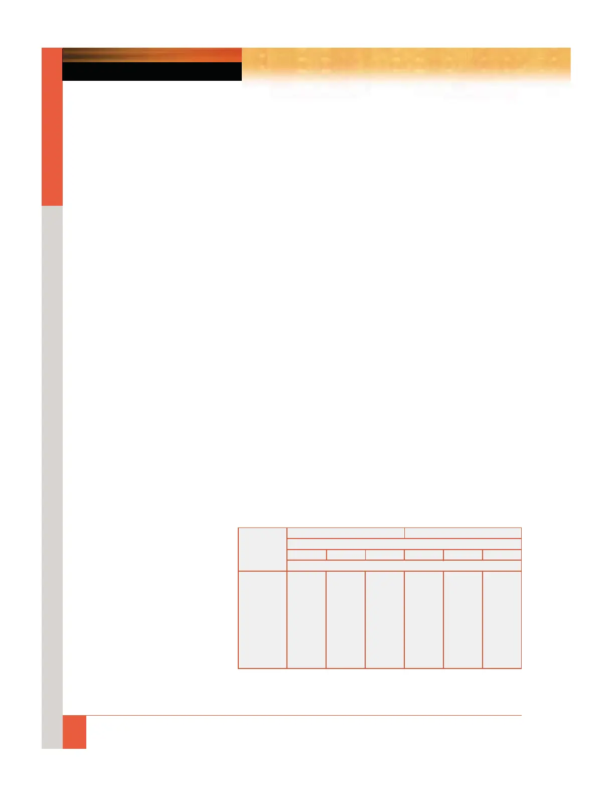
Ratings
SB-1 Switches are rated for a
mechanical life of one million
operations. The electrical ratings
are 600 VDC and VAC, 20 A
continuous, or 250 A for three
sec. The interrupting rating
depends upon the voltage and
character of the circuit, and the
number of contacts connected in
series, as indicated in the table.
Contacts can be paralleled when
current exceeds 20 A.
Circuit Volts
Noninductive Circuit
➀ Inductive Circuit
Number of Contacts
1 2 in Series 4 in Series 1 2 in Series 4 in Series
Interrupting Rating (A)
24 DC 6 30 … 4 20 30
48 DC 5 25 40 3 15 25
125 DC 2.5 11 25 2 6.25 9.5
250 DC .75 2 8 .7 1.75 6.5
600 DC .25 .45 1.35 .15 .35 1.25
115 AC 40 75 — 24 50 …
220 AC 25 50 — 12 25 40
440 AC 12 25 — 5 12 20
550 AC 6 12 — 4 10 15
➀ Values of inductance equal to that of the average trip circuit. For circuits
having high values of inductance, refer application to your GE representative
for recommendations.
INTERRUPTING RATINGS
 Loading...