Electroswitch • 180 King Avenue • Weymouth, MA 02188 • TEL: (781) 335-5200 • FAX: (781) 335-4253 • www.electroswitch.com
45
FEATURES
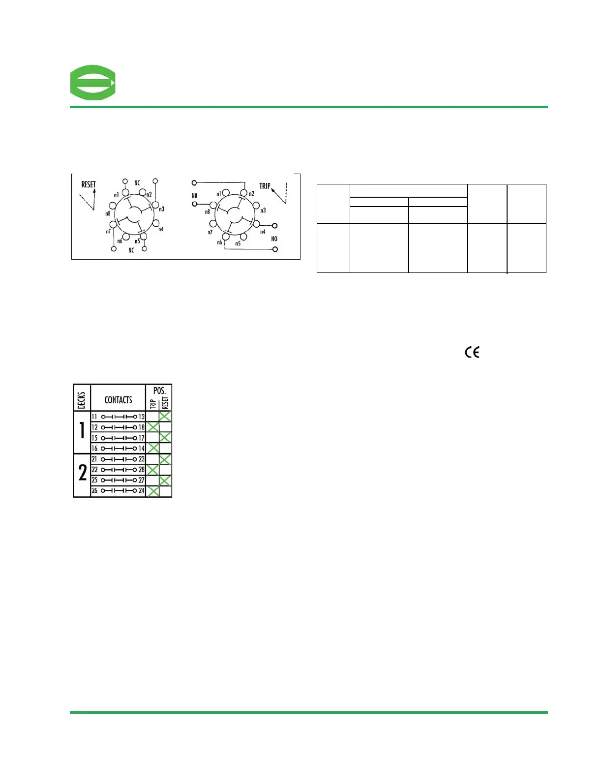
Typical Contact Deck Arrangement
The blade and terminal configuration enables the use of multiple contacts in the same deck,
and simple stacking procedures enable the fabrication of many independent contacts in one
relay. Specifically, two N/O contacts and two N/C contacts are provided in each deck, and up
to ten decks can be stacked, resulting in a relay with up to forty contacts (twenty N/O and
twenty N/C). For good practice, however, it is suggested that polarized voltages should
not be used on adjacent contacts. This is because of the remote possibility of flashover
during transition between adjacent contacts -- especially at the higher DC ratings, or in
highly inductive circuits. The illustration shows a single deck. For multideck units the second
digit of the terminal number is the same as shown, but the first digit changes to denote the
deck number. As an example, terminal 82 is in the eighth deck, directly under terminal 12 and
is connected to terminal 88 in the trip position.
The interrupting ratings are based on a 10,000 operation life at rated voltage with no exten-
sive burning of contacts. Short time and continuous ratings are based on temperature rise in
contact members and supporting parts not to exceed 50˚ above ambient.
UL file No. E80080 • IEEE Std. 323 - 1984 •
• IEEE Std. 344 - 1987
Contact Ratings
Contact ratings for LOR
SERIES 24 LOCK-OUT RELAYS
Basic LOR Deck Layout
125VDC
250VDC
120VAC
240VAC
480VAC
600VAC
5
3
20
15
7.5
6
2
1
20
10
5
5
Short Time
Rating**
(AMPS)
Continuous
Rating
(AMPS)
60
60
60
60
60
60
30
30
30
30
30
30
Single
Contact
Single
Contact
Contact
Circuit
Volts
Interrupting Rating (AMPS)
Contact Charts
The illustration shows decks one and two of a
typical Series 24 LOR and graphically describes
the operation of the contacts.
Trip Speed in Lock-Out Relays
The manual reset Series 24 LOR has a nominal trip speed of less than 8 milliseconds at rated
voltage as tested on 10 deck units. There is very little difference in LORs with fewer decks.
Both the Electric Reset and the Self Reset LORs are available in Standard Trip and
High-Speed Trip configurations.
•
models operate in approximately 12–15 mSec and come equipped with the
standard LOR target nameplate or the optional LOR Monitor Nameplate.
•
LOR/ER models have the same 8 mSec trip speed as the Manual Reset
LOR and come equipped with the Memory Target which displays an orange flag until it is
manually reset.
•
with multiple LED indicators is available for all Series 24 LORs.
Target Used with Lock-out Relays
All the Lock-out Relays have a mechanical target as part of the nameplate – BLACK for RESET
and ORANGE for TRIP. This indicates the condition of the LOR. The target resets when the LOR
resets (with the exception of the high-speed trip electric-reset LOR/ER and self-reset LOR/SR
where the memory target is manually reset).
Resistive Inductive*
* AC PF = 0.4; DC L/R = 0.04 ** Short time current is for one minute
 Loading...