Electroswitch • 180 King Avenue • Weymouth, MA 02188 • TEL: (781) 335-5200 • FAX: (781) 335-4253 • www.electroswitch.com
SERIES 24 LOCK-OUT RELAYS
Selecting a Series 24 Lock-Out Relay:
1. Select type of LOR (Manual Reset, Electric Reset or Self Reset).
2. Fill out appropriate ordering matrix.
3. When selecting Trip and Reset Coils use information from tables below.
4. Contact factory for custom features and nonstandard configurations.
Manual Reset LOR
Model
78 = LOR
Trip Coil
(See Page 47)
A=Coil A
B = Coil B
C=Coil C
D=Coil D
E=Coil E
F=Coil F
G=Coil G
H=Coil H
K = Coil K
03 = 3
05 = 5
08 = 8
10 = 10
No. of Decks
Electric Reset LOR/ER
Model
78 = LOR
Trip Coil
(See Page 47)
A=Coil A
B = Coil B
C=Coil C
D=Coil D
E=Coil E
F=Coil F
G=Coil G
H=Coil H
K = Coil K
No. of Decks
3=3
5 = 5
8 = 8
(10 Consult Factory)
Reset Coil
A = 24VDC
C = 48VDC
D = 125VDC
F = 250VDC
2 = Std. Trip LOR/ER
3 = Hi-Spd. Trip LOR/ER
Configuration
ORDERING INFORMATION
Self Reset LOR/SR
Model
78 = LOR
Trip Coil
D, E, F, G Available for Std. Trip LOR/SR
D, E, F
Available for Hi-Spd. Trip LOR/SR
No. of Decks
3=3
5 = 5
7 = 7
(time delay units only)
8 = 8 (instant reset units only)
Reset Coil
D = 125VDC
4 = Std. Trip, Instant Reset,
LOR/SR
5 = Std. Trip, T
ime Delay Reset,
LOR/SR
6 = Hi-Spd. Trip, Instant Reset,
LOR/SR
7 = Hi-Spd. Trip,
Time Delay Reset, LOR/SR
Configuration
78
78 D
78
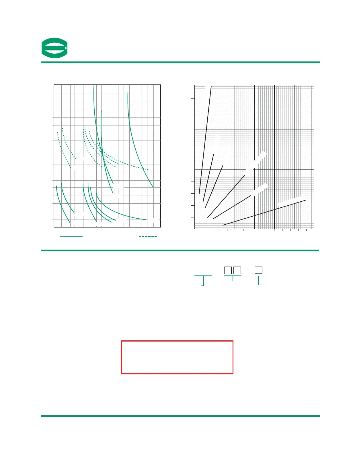
LOR RESPONSE TIMES*
10 20 30 40 50 20 40 60 80 100 120 140 160 180 200 220 240 260 280 300
24
23
22
21
20
19
18
17
16
15
14
13
12
11
10
9
8
7
COIL A
COIL B
COIL A
COIL B
COIL F
COIL H
COIL D
COIL E
COIL C
COIL C
DC VOLTS
MILLISECONDS @ 20°C
COIL D
COIL E
COIL K
COIL G
COIL F
Time to Close Normally Open Contacts
COIL A - 3.3Ω
COIL B - 7.7Ω
COIL C - 13Ω
COIL E - 50Ω
COIL F & H - 104Ω
COIL D, G & K - 27Ω
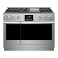
20 40 50 60 80 100 120 140 160 180 200 220 240 260 280
DC VOLTAGE APPLIED TO COIL
DC AMPERES @ 20°C
12
11
10
9
8
7
6
5
4
3
2
1
LOR CURRENT
Voltage Characteristics Of The Trip Coils
48
*For AC Applications refer to Trip Coil Voltage Data on page 47
LOR LOR/ER, LOR/SR
This Project
7803D