8
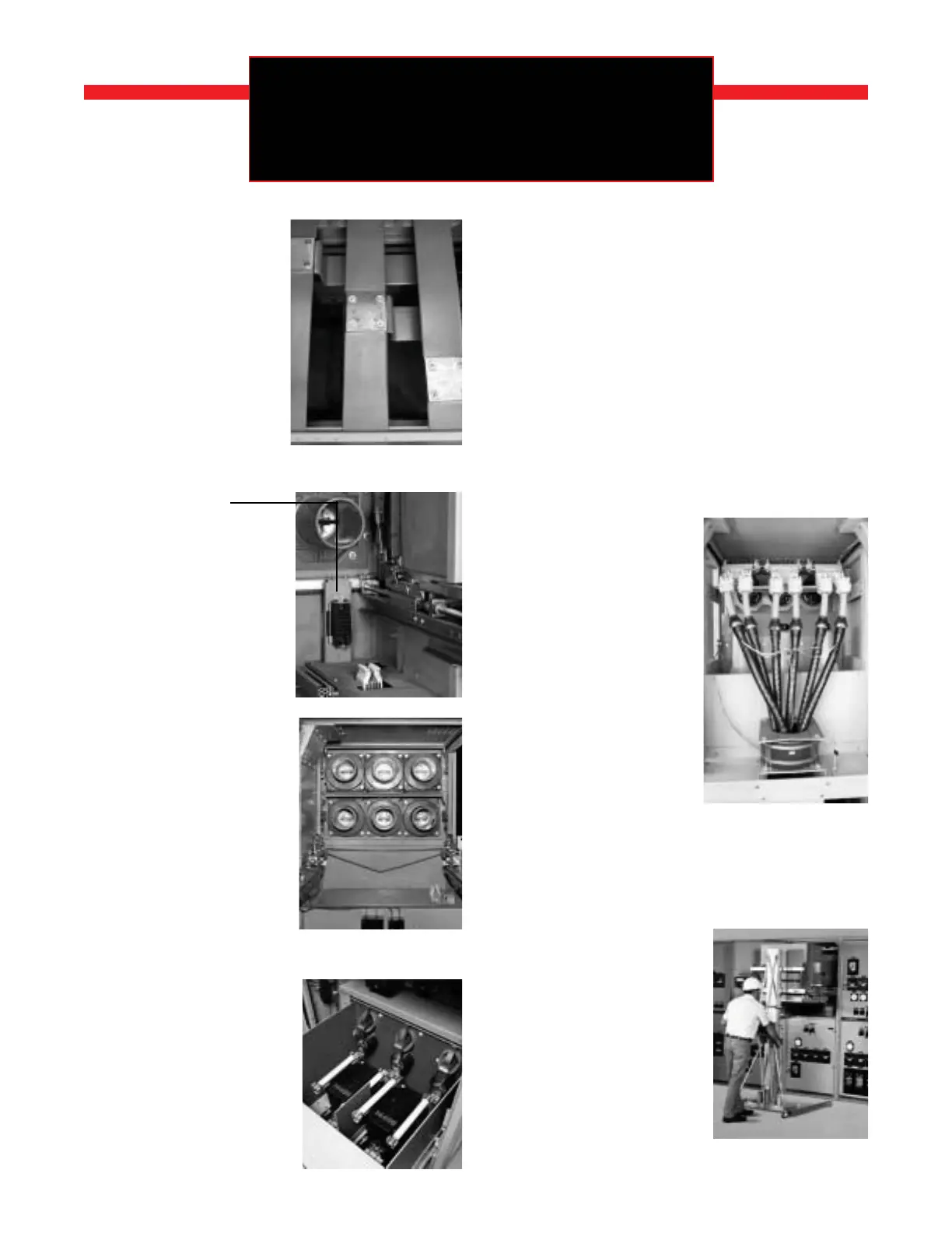
A. MAIN BUS
COMPARTMENT
is completely isolated by 11
gauge metal barriers. Bus bars
are provided with high dielectic
epoxy insulation and pass
through track-resistant polyes-
ter glass barriers between cu-
bicles. All main bus is fully tin-
plated after fabrication for posi-
tive contact and low resistance,
and are insulated with per-
formed boots (not shown in this
photo). Porcelain insulation to
ground and silver plating are
optional.
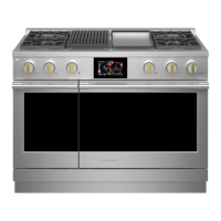
B. SECONDARY
DISCONNECTS
combine the positive-contact
reliability of a plug with the au-
tomatic, self aligning conve-
nience of sliding-type contacts.
While in the test position, sec-
ondary contacts are easily dis-
engaged or rengaged by a link-
age operated from the front of
the circuit breaker.
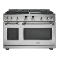
C. CURRENT
TRANSFORMERS
are
typically located behind me-
chanically actuated safety shut-
ter and barrier that isolates the
primary disconnects as the
breaker is moved into the DIS-
CONNECT position. Two stan-
dard accuracy CTs per phase
can be accomodated on both
the line and load sides of the
breaker (as many as 12 CTs per
breaker). CTs are front acces-
sible after removal of the safety
shutter barrier and barrier.
D. VOLTAGE
TRANSFORMERS
meet
all applicable industry stan-
dards and are mounted in an
easy-access roll-out tray. VTs
are automatically grounded
upon withdrawl, tray provides
isolation from primary connec-
tions.
E. DRY TYPE
CONTROL POWER
TRANSFORMERS
have molded epoxy resin insu-
lation and are mounted in a
draw out tray for easy access.
Ratings run through 15kVA
single phase. When a higher
rating, or 3 CPTs, are required,
a key interlocked fused roll-out
tray will be supplied with sta-
tionary CPTs mounted in the
rear of
the unit.
F. CABLE
COMPARTMENT
in a basic two-breaker vertical
section has ample space for
termination of up to two 750
MCM cables per phase, includ-
ing stress cone makeup. When
only one breaker is required in
a vertical section, the entire
cable space is available for use.
In two-high breaker equipment,
a vertical steel trough serves as
a seperation barrier from the
other cable compartment. This
duct is easily removed to facili-
tate initial installation of the
inside cables. When the
vertical steel duct is in place,
there is still access to the
inside terminations. The
power cable compartment can
be arranged to permit both sets
of cables to exit below or
above.
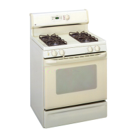
G. PORTABLE
BREAKER LIFT
is provided for handling a
breaker or roll-out during instal-
lation into a compartment, or
during removal for inspection
or maintenance. Lifts for both
indoor and outdoor equipment
have interlocks on the lifting
forks to lock the breaker in place
during transporting.
f
THESE SUPERIOR DESIGN
FEATURES ARE STANDARD ON
POWER/VAC
®
SWITCHGEAR