INSTALLATION
P485 MODBUS TO PROFIBUS CONVERTER – USER GUIDE 2–5
Mechanical installation
DIN-RAIL MOUNTING The DIN-rail connector is internally connected to the P485.
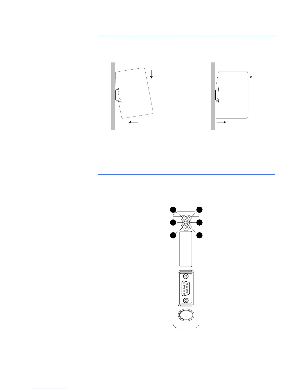
Figure 2-8: Mounting the P485 to the DIN-rail
To snap the P485 on, first press the P485 downwards (1) to compress the spring on the DIN-
rail connector, then push the P485 against the DIN-rail as to make it snap on (2)
To snap the P485 off, push the P485 downwards (1) and pull it out from the DIN-rail (2), as to
make it snap off from the DIN-rail.
Indicators and switches
STATUS INDICATORS The status indicators for the P485 Modbus to Profibus Converter are indicated below.
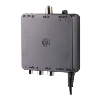
Figure 2-9: P485 status indicators
11
22
ON OFF
1
3
5
2
4
6