P485 MODBUS TO PROFIBUS CONVERTER – USER GUIDE 3–1
GE Consumer & Industrial
P485 Modbus to Profibus
Converter
Chapter 3: Data exchange
Data ex change
Overview
DESCRIPTION Data from the fieldbus (Profibus) and the sub network (Modbus) is stored in an internal
memory buffer. This is a easy method for data exchange where the fieldbus control
system simply reads and writes data to pre-defined memory locations, and the serial sub
network also use the same internal memory buffer to read and write data. Refer to Figure
3-2: Data exchange overview on page 3–2 for details.
INTERNAL MEMORY
BUFFER STRUCTURE
The internal memory buffer can be seen as a memory space with three different types of
data; input data, output data and general data.
• Input data: This is data that should be sent to the fieldbus. The P485 can handle up to
244 bytes of input data. The total input/output data must not exceed 416 bytes.
• Output data: this is data recieved from the fieldbus. The P485 can handle up to 244
bytes of output data.
• General data: This data cannot be accessed from the fieldbus, and is used for
transfers between nodes on the sub-network, or as a general “scratch pad” for data.
The P485 can handle up to 1024 bytes of general data.
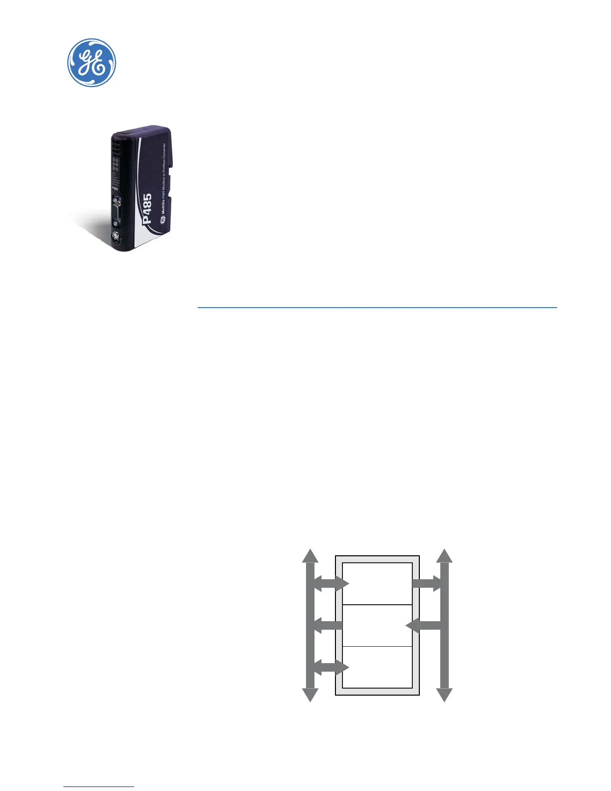
Figure 3-1: Internal memory buffer
Internal Memory Buffer
Output data
(up to 244 bytes)
Input data
(up to 244 bytes)
Sub Network
Fieldbus
General data
1024 bytes