Power Break
®
Circuit Breakers
Chapter 3. Accessories
11
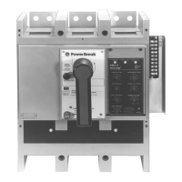
Figure 18. 1600–2000 A frame electrically operated breaker.
Figure 19. 1600–2000 A frame electrically operated breaker with the
outer cover removed.
Breaker Cover Reassembly
Manually Operated Breakers
11
11
..
..
Verify that all connections are secure and the breaker
is free of debris.
22
22
..
..
Verify that the breaker is off.
CC
CC
AA
AA
UU
UU
TT
TT
II
II
OO
OO
NN
NN
::
::
Verify that the accessory mounting plate
insulator, shown in Figure 20, is properly located so it
will not be damaged when the cover is replaced. The
cover phase barrier must pass to the right side of this
insulator.
33
33
..
..
Position the charging handle at the home position (6
o’clock) on the cover. Align the cover mounting
screw holes with the breaker base and install the four
cover screws. Tighten the screws to 50–60 in-lbs.
Figure 20. Wire ties on the accessory leads and mounting plate
insulator.
Electrically Operated Breakers
11
11
..
..
Verify that all connections are secure and the breaker
is free of debris.
CC
CC
AA
AA
UU
UU
TT
TT
II
II
OO
OO
NN
NN
::
::
Verify that the accessory mounting plate
insulator is properly located, as shown in Figure 26.
22
22
..
..
Slide the inner cover assembly onto the breaker base.
Ensure that the crossbar hook engages the drive stud,
as shown in Figure 21.
Figure 21. Crossbar hook engaging the drive hook.
33
33
..
..
Tighten the inner cover lock screw, shown in Figure
19, to 10 in-lbs.
44
44
..
..
On 1600–2000 A frame breakers only, replace the two
inner cover mounting screws and tighten to 50–60 in-
lbs.